
Users Manual Part 1


Page 11 of 21
Chapter4Applicationnote
4.1Antennadesignguide
If you have high requirements for communication distance, an external antenna can be
used. The IO port required to use the external antenna is PIN18 (ANT). The original
antenna position under the module must be completely copper。
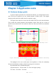
The figure below shows the circuit from the module ANT Pin to the external antenna.
The red thick line should guarantee 50Ω impedance control. Keep the line as short as
possible, do not hit the hole, do not take the acute line. Place more GND vias around the
RF traces.
Figure 4-1 Schematic diagram of external antenna impedance matching circuit
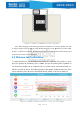
Figure 4-2 External antenna impedance matching circuit PCB schematic and routing
instructions
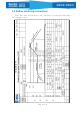
The highlight of the trace sould control the impedance of 50Ω, the relationship
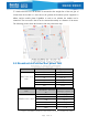
between board thickness and line width, line spacing can be referred to:
Recommended value of FR4 Double panel:
(H=plate thickness,W=line width,D= Trace and copper spacing)
H=1.0mm,W=0.8mm,D=0.2mm