
Installation Manual
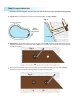
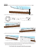
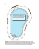

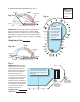

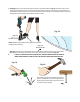


Fig. 5
Fig. 5a
Fig. 6
2
2
3
Fig. 7
3
4
4
Once both holes of the start point are marked, (1L & 1R) place the template provided over 1R Fig. 5.
Then place the template over 1R and mark your second hole for that section (Fig. 5a).
Now repeat until the 5th pole of the section Fig. 6-7a
Mark your last hole for that section, (hole 5) Fig. 7a.
Fig. 7a
5
Then use the double hole on the template and align it over the 5th hole you marked Fig. 7b and mark the
rst hole of the next connecting section to the right, (hole 1). Repeat these steps on both sides of the
pool until you reach the section that will be the cut section.
Mark-Out:
Slide Template 1/4”
Placed Over
Previous Hole
Placed Over
Previous Hole
** See Fig. 8 on the next page for the full lay out example.
3’
1R
1L
1R
1L
4
Fig. 7b
5
1