S C R A T C H C O D I N G K I T Logic boost CODING CLASS CLASS forever imagine program share 3
CLASS 3 Before getting started The computer programmer is the creator of the universe, who is responsible for it. This allows infinite and complex forms of space to be created in the form of computer programs.
S C R A T C H C O D I N G Contents To begin 1 …………………………………………………………………………………………………………… Lesson 1. IR sensor …………………………………………………………………………………………… 4 Lesson 2. Nested ‘if’ syntax ………………………………………………………………………………… 14 Lesson 3. IR sensor utilization ………………………………………………………………………… 30 Lesson 4. Line Follower ……………………………………………………………………………………… 37 Lesson 5. DJ box ………………………………………………………………………………………………… 48 Lesson 6. Ultrasonic sensor ………………………………………………………………………………… 59 Lesson 7.
CLASS 3 To begin Welcome to CLASS ! You know how to use products of ROBOTORI yesterday and what are the essential elements of programming concepts. In this book, we'll look at some of the more intensive programming steps you need to make more complex robots. At this level, we will learn more advanced coding with IR sensors and ultrasonic sensors as input sensors.
S C R A T C H S C R A T C H C O D I N C O D I N G G K I K I T T Logic Boost Infrared Sensor IR SENSOR LESSON 1
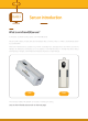
CLASS 3 Sensor introduction What is an infrared(IR)sensor? In this lesson, you'll learn the input sensor, the infrared (IR) sensor. We can use IR to detect an object and pass the detected value to the input value. It's similar to the brightness sensor you covered earlier. When the infrared sensor is covered by your hand, the analog input value goes down, and when your hand is released, the analog input value goes up. It's the opposite of the brightness sensor.
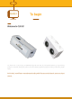
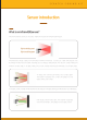
S C R A T C H C O D I N G Sensor introduction What is an infrared(IR)sensor? The infrared sensor consists of two parts: a light emitting part and a light receiving part. light emitting part light receiving part Infrared sensors detect objects by illuminating invisible infrared rays. It consists of a light emitting part that illuminates infrared rays and a light receiving part that detects reflected light. The amount of light reflected is different for each object.
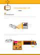
CLASS 3 Connecting Main Cell Connecting IR sensor Now we will connect the infrared sensor to the main cell. Plug the 3-pin connection jack into the infrared sensor as shown below. “S” = White “+” = Red “-” = Black Please check that the sensor does not work if you do not connect it correctly according to the cable color as shown above. Attach the sensor to slot 7 of the board.
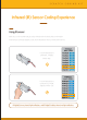
S C R A T C H C O D I N G Infrared (IR) Sensor Coding Experience Using IR sensor Now, let's turn on the main cell, go scratch and see how the sensor gives us information. If everything is connected properly, cover the infrared sensor with your hands and remove it. If the infrared sensor is still present, "Digital2" will be 'false'. If the infrared sensor is covered by your finger, "Digital2" will be 'true'.
CLASS 3 Infrared (IR) Sensor Coding Experience Using IR sensor Connect the infrared sensor cell as shown in the figure below. Slowly pull the infrared sensor along the pattern below. Then write it in the blank, whether the sensor is true or false.
S C R A T C H C O D I N G Infrared (IR) Sensor Coding Experience Using IR sensor Now I'll see how you can apply an infrared sensor to your program. First, we have to make our old friend, a mini windmill. Now you can make this model very quickly.
CLASS 3 Infrared (IR) Sensor Coding Experience Using an infrared sensor with a mini windmill We will use the infrared sensor to operate the mini windmill. First, we need a way to get the "true" and "false" values of an infrared sensor with scratches. To do this, go to the Motion tab and import the "Sensor digital 2 pressed" block into the script as shown below.
S C R A T C H C O D I N G Infrared (IR) Sensor Coding Experience Coding a mini windmill with an infrared sensor Just as you learned with the button sensor, you can see that the digital value is 'true' when the infrared sensor is covered and the digital value is 'false' when it is off. Now, let's see how to operate the motor using an infrared sensor instead of a button sensor. Plug the DC motor into the 'Motore4' port on the main board. Create a script like the one above.
CLASS 3 Infrared (IR) Sensor Coding Experience Coding a mini windmill with an ir sensor In the flowchart, you can see that the digital input value is the same as the button sensor. Program in! ga A k ec h C Turn on the motor Ch ec kA ga in! start True Is the IR sensor False true or false? Turn off the motor STOP When you put your finger on the infrared sensor, the motor will turn on. If not, the motor turns off.
S C R A T C H S C R A T C H C O D I N C O D I N G G K I K I T T Logic Boost Nested ‘if’ syntax LESSON 2
Introduction CLASS 3 'If' syntax in 'if' syntax This time we will learn the 'if' syntax in more detail. Is it hot outside? No Yes Do you want to eat something sweet? Yes I eat ice cream No Don't eat ice cream The end We eat ice cream when we want to eat sweets or it’s hot and we don’t otherwise. Here we need two 'if' statements. First, I'll check to see if it's hot outside and the second time I want to eat sweet.
S C R A T C H C O D I N G Introduction Nesting 'if' syntax in scratch Let's see how the ice cream case turns into a scratch. It’s very hot if If the weather is cold and if we want sweets, we'll have I eat ice cream ice cream. If we do not else want sweet, we will not eat I don't eat ice cream ice cream. I eat ice cream else if even if we want something sweet.
Introduction CLASS 3 Create your own quotes ‘if’ syntax example Now write your own 'if & else' syntax example here Yes No Yes No The end Create your own ‘if’ syntax example Now convert your example to scratch if if else else if else
S C R A T C H C O D I N G Making a Robot Making the Bot Come We'll make a robot that follows your hand to understand the nested 'if' syntax.
CLASS 3 Making a Robot Making the moving bot 1 1-1 1-2 x4 x1 x1 x2 x2 x2 Figure 1-2 1-3 45 degree angle 1-4 x4 Figure 1-1 2 2-1 Figure 1-3 Combine figure 1-1 and bottom figure 1-2 Make two of these Figure 2-1 2-2 Figure 1-4 x2 x2 Assemble figure 1-4 and x2 2-3 figure 2-1 Figure 2-2 A 45 x2 A 45 x2 A 45
S C R A T C H C O D I N G Making a Robot Making the moving bot 3 3-1 Figure 2-3 3-2 x2 A 23 x2 Figure 3-1 Make two of these 3-3 A Figure 3-3 3-4 A x2 x2 x2 4 Figure 3-2 x2 B 4-1 B Figure 3-3 4-2 x1 x4 x1 Figure 3-4 4-3 Figure 4-1 x2 Figure 4-2 K I T
Making a Robot CLASS 3 Making the moving bot 5 5-2 A 23 A B A Figure 5-1 B Figure 5-1 x2 x2 x2 x4 x4 A 64 x2 A 23 x2 A 64 A Figure 5-2 5-3 A B Figure 5-2 B Figure 4-3 5-4 x2 x2 * caution A B A Figure 5-3 B Figure 5-3 6 x2 x2 7 x2 x1 x2 x3 x1
S C R A T C H C O D I N G Learning Coding of Moving Bots Making the moving bot 8 Right IR SENSOR ※ Please refer to the sensor connection status of the moving bot shown below.
CLASS 3 Learning Coding of Moving Bots Programming the Moving Bot Unlike the one we used before, we'll use the infrared sensor as the "eye" of a moving bot. When you cover the left sensor, the robot goes to the left. Connect to Digital 3 Connect to Digital 2 Cover the right sensor and the robot will go to the right.
S C R A T C H C O D I N G Learning Coding of Moving Bots Programming the Moving Bot If both infrared sensors are covered, the coming bots are moving forward. To make our moving bots perform four different actions (left, right, forward, and stop), we need the 'if' syntax many times.
CLASS 3 Learning Coding of Moving Bots Programming the Moving Bot If we wanted to write four programs to control the moving bots, the flow chart would look like the one below.
S C R A T C H C O D I N G Learning Coding of Moving Bots Programming the Moving Bot Combine four different programs into a single flowchart. Think of an infinite loop in the flowchart.
CLASS 3 Learning Coding of Moving Bots Programming the Moving Bot Your flowchart will look like this: Think of the flowchart as having an infinite repeat block.
S C R A T C H C O D I N G Learning Coding of Moving Bots Programming the Moving Bot Let's take a look at the scratch code below and see how the moving bots move. If the left infrared sensor and the right infrared sensor are covered, the coming bots are moving forward. If you cover only the left infrared sensor, the coming bots will move to the left. If the left infrared sensor is not covered and the right sensor is covered, the humming bots will move to the right.
CLASS 3 Learning Coding of Moving Bots Programming the Moving Bot Now we need an infinite loop and a start block to complete the code. You can now make a moving bot that follows.
S C R A T C H S C R A T C H C O D I N C O D I N G G K I K I T T Logic Boost IR Sensor Utilization LESSON 3
CLASS 3 Connecting Main Cell Connecting an IR sensor to an Analog port Connect the infrared sensor to the analog port of the mainboard 1 2 3 4 5 6 7 8 B R W 0 1 2 3 4 5 Analog input Plug the infrared sensor into the port and check the values below! You can see that the value of the Analog0 port changes! This is the analog value of the infrared sensor. When you cover the infrared sensor with your fingers and release it again, you can see that the value goes down and then goes up again.
S C R A T C H C O D I N G IR Sensor coding practice Analog value of IRsensor Keep your infrared sensor flat on the bottom of the gradient box. You will find that the analog output values change slowly. Write down the values from each specific point in the empty bin below.
Making a Robot CLASS 3 IR sensor Analog Meter We will now use servo motors to display the values of the infrared sensors.
S C R A T C H C O D I N G Making a Robot Making a Meter 1 1 2 11 x2 x2 1 1 x2 x 2 x2 x1 x1 x2 x 1 x1 x1x1 A64 x1 A64 x1 x1 x1 A A64 64 x1 x1 A64A64 x1 x1 x1 x1 x1 x1 3 3 3 x4 x4 3 3 3 x4 2 2 2서보 Combine them with the angles shown below 이 각도로 붙이세요! 붙이세요! 2 이 각도로 서보 모터 서보 모터 모터 2 이 각도로 붙이세요! 서보Servo motor 이 각도로 붙이세요! Step 1이 각도로 붙이세요! Step 서보 1 모터 모터 1 Step Step 1 Step 1 4 4 4 4 44 x4 x4 x4 Step33 Step33 Step Step Step 3 완성 완성완성 완성 Complete 완성 Step 3 Step Step Step 33 3 Step
CLASS 3 Coding a Meter Coding a Meter Like digital blocks, there are blocks that represent analog values. As we learned earlier, the servomotor operates according to the angle the user commands. Try to operate the servo motor according to the value of the infrared sensor. If the infrared sensor value is 0, the servo motor will move to 0, and if the infrared sensor value is 180, the servo motor will move to 180 degrees.
S C R A T C H C O D I N G Coding a Meter Coding a Meter Drag the infrared sensor along the bottom gradation piece to see if the servomotor is acting as a meter.
S C R A T C H C O D I N G K I T Logic CLASS 3 Boost Line Follower LESSON 4
S C R A T C H C O D I N G Making a Robot Activity Introduction Now we're going to make line followers with what we've learned about operators and thresholds.
Making a Robot CLASS 3 Making a line follower 1 1-1 1-2 x1 x1 x2 x2 x2 A 45 1-1 x2 같은 모형을 2개 같은 모형을 2개 만들어줍니다. 만들어줍니다. 2 2-1 같은 모형을 2개 같은 모형을 2개 같은 모형을 2개 모형을 같은같은 모형을 2개2개 만들어줍니다. 같은 모형을 2개 만들어줍니다. 만들어줍니다. 만들어줍니다. 2-2 만들어줍니다. 만들어줍니다. x6 같은 모형을 2개of these Make two 만들어줍니다. x2 3 x2 1-2 3-2 모형을 2개 Make two of these 같은 3-1 같은 모형을 같은 모형을 2개2개 같은 모형을 2개 같은 모형을 2개 만들어줍니다. 만들어줍니다. 만들어줍니다. 만들어줍니다. 같은 모형을 x만들어줍니다. 2 2개 같은 모형을 모형을 2개 같은 2개 만들어줍니다. 같은 모형을 2개 만들어줍니다. 만들어줍니다.
S C R A T C H C O D I N G Coding Line Follower Making a line follower 4 4-1 4-2 4-1 3-4 x2 x2 x2 5 5-1 5-2 x1 x1 x1x 1 x1 x1 x1 x1 x1 x1 x1 x1 x1 x1 x1 6 오른쪽 오른쪽 오른쪽 Right 모터 모터 오른쪽 모터 motor 모터 Left motor 왼쪽모터 왼쪽모터 왼쪽모터 왼쪽모터 Connects to left motor 왼쪽모터 왼쪽모터 왼쪽모터 연결 연결 연결 왼쪽모터 연결 Connect to right motor 오른쪽모터 오른쪽모터 오른쪽모터 연결연결 연결 오른쪽모터 연결 K I T
CLASS 3 Coding Line Follower Coding a Line Follower Code line followers. Line followers will use infrared sensors to find black lines. The infrared sensor can tell if the car is on the line. The program will use the following logic to move the car along the line. Left motor 1. If the infrared sensor is on the black line, the car will activate the right motor and break it to the left. Right motor 2.
S C R A T C H C O D I N G Coding Line Follower Coding a Line Follower That is, when the infrared sensor detects the line (the black area absorbs the light and the light is less reflective), the line follower will move out of the left line. If the infrared sensor no longer detects the line (if there is a lot of light reflection), the line follower will move to the right. The infrared sensor will detect the black area again and go to the left. This cycle repeats until the line follower follows the line.
CLASS 3 Coding Line Follower Coding a Line Follower The program will check whether the infrared sensor is on the line or not and move accordingly. Check the flowchart below and think of the program as having repetition.
S C R A T C H C O D I N G Coding Line Follower Coding a Line Follower Write down the program step by step. First, write down when the infrared sensor value is on the line. Use the black line below. The value when the infrared 적외선 센서가 위에 sensor선 is on line 있으면 값은… The센서가 value when the infrared 적외선 선 밖에 있으면 sensor is out of line 값은… First, we need the 'if' syntax to tell us what to do if the infrared sensor is on the line.
CLASS 3 Coding Line Follower Coding a Line Follower The next code to make is when the infrared sensor is out of line If the infrared sensor value is low (the infrared sensor is outside the line), you should turn the left motor on and move the car to the right until the infrared sensor is above the line. Combine the two programs and add an "Forever" block.
S C R A T C H C O D I N G Use this page as long as you want the line follower to move.
CLASS 3 Coding Line Follower Replace IF statement with IF and Else statement In the previous code, we wrote two 'if' statements to make the code work. We can replace two 'if' statements with a 'if & else' statement. Try it! ※The whole script can be found at http://www.robotori.com/web_eng -> Moretips -> Manual ->EDU ->Logic boost CODING CLASS 3 ->download whole script Use electric tape to create your own tracks that will follow your line followers.
S C R A T C H S C R A T C H C O D I N G C O D I N G K I K I T T Logic Boost DJ Box LESSON 5
CLASS 3 Conditional Operator Introduction Here you are going to first learn the conditional operator to make a DJ box. Conditional operators are operators that compare different conditions. Look at the conditional operator below. Condition 'and' -condition 'and' must satisfy both left and right conditions. Look at the example of the conditions 'and' below. = false true + false The reason the above condition is false is that the left condition is true but the right condition is false.
S C R A T C H C O D I N G Conditional Operator Introduction Condition 'or' -condition 'or' is true if only one of the left or right is true. See the example of the condition 'or' below. = true true + false In the condition 'or', the left is true and the right is false. Because one condition is true = true true + true In the example above, both conditions are true, so the whole condition is true.
CLASS 3 Conditional Operator Introduction Condition 'Not' - Condition 'Not' is true if the condition in is false. Look at the examples below for the condition 'not' = true false The condition is not true because the condition above is false. = false true The condition is not true because the condition inside is false.
S C R A T C H C O D I N G Making a Robot DJ Box Utilizing the knowledge of conditional operators, we are now going to make a DJ box that uses an infrared sensor to make the instrument sound. Use the picture below to create a DJ box.
CLASS 3 Coding the DJ Box DJ BOX Below is the gradient box from white to black. Move the DJ box's infrared sensor near the gradient to see how the value changes. Write down the values when the infrared sensor reaches A, B, C, D, and E points. A B C D E The DJ box will play a different drum sound when the infrared sensor passes through each part of the gradient box shown above.
S C R A T C H C O D I N G Coding the DJ Box Coding the DJ Box If you have exhausted the infrared sensor values, we will make the DJ box play different bits as the infrared sensor shows. Scratch can make a lot of sound including drum beat. Go to the palette and choose Sound template. Bring a block that looks like this Make sure you hear sound from your computer and click on the block. You can hear the drums on your computer. If you want to hear other drum sounds, try changing the value of the drum.
CLASS 3 Coding the DJ Box Coding the DJ Box Here are the programs you need to create. Now run the program. If you move the infrared sensor to the left of the "C" value, you can hear the drum sounds. Now we are going to code a program that sounds multiple drums simultaneously at A, B, D and E values. To do this we need logical conditions. See the flowchart below..
S C R A T C H C O D I N G Coding the DJ Box Coding the DJ Box If you want to play a particular beat between the B and C values with your DJ box, you have to write down the condition. B C This means that the infrared sensor value must be greater than B and less than C. Look at the code below. The condition shows that the IR value must be greater than B and less than C to be true unconditionally. If not, I will not play drum beat.
Coding the DJ Box CLASS 3 Coding the DJ Box Now let's repeat the above steps to make bits of the other region. We have to create three more bit areas, one between "A" and "B", between "C" and "D" and finally "D" and "E". Here's a logical flowchart, but you can create the rest of the program yourself. The IR sensor value is larger than 'A' and YES smaller than 'B'. Play an unique beat NO The IR sensor value is larger than ‘B' and YES smaller than ‘C'.
S C R A T C H C O D I N G Coding the DJ Box Play the DJ Box Now play the beat you created! A B C D E K I T
S C R A T C H C O D I N G K I T Logic CLASS 3 Boost Ultrasonic Sensor LESSON 6
S C R A T C H C O D I N G Introduction What is an Ultrasonic Sensor? Now let's look at the ultrasonic sensors, one of the input sensors that measure distances. An ultrasonic sensor is a sensor that sends ultrasonic waves to a specific object and receives the reflected ultrasonic waves to detect the distance of the object. The value of the scratch input depends on the distance the ultrasonic sensor measures.
CLASS 3 Connecting the Main Cell Connecting the ultrasonic sensor to the analog port. Try connecting the ultrasonic sensor to the analog port of the motherboard. 1 2 3 4 5 6 7 8 B R W 0 1 2 3 4 Analog input S “-” = Black + “S” = White “+” = Red Insert the ultrasonic sensor into the port and check the values below. You can see that the value of Analog0 port changes on the screen. This is the analog value of the ultrasonic sensor.
S C R A T C H C O D I N G Ultrasonic Sensor Coding Experience Ultrasonic Sensor Analog Value If you leave the ultrasonic sensor, you can see the value of "Analog0". As you get closer to the ultrasonic sensor, you can see that the value of "Analog0" decreases Unlike the sensors you learned earlier, ultrasonic sensors do not cover or press them by hand, but they use values based on distance, making it difficult to use them as digital values.
CLASS 3 Ultrasonic Sensor Coding Experience Utilizing the Ultrasonic Sensor Now let's see how we can apply an ultrasonic sensor to our program. First, we have to make our old friend, a mini windmill.
S C R A T C H C O D I N G Ultrasonic Sensor Coding Experience Using the Ultrasonic Sensor with the Mini Windmill We will use ultrasonic sensors to operate the mini windmill. I will operate the mini windmill according to the distance between the ultrasonic sensor and the object. Code it so that when the distance approaches the windmill works, and stops if it goes away.
CLASS 3 Ultrasonic Sensor Coding Experience Coding the mini windmill with ultrasonic sensor You have to set the distance standard to check the analog value of the ultrasonic sensor. Do you remember the threshold you learned at level 3? The mini windmill should work if you get the distance standard and closer to it, and the mini windmill should not work if it is farther than the standard. This will be the script below.
S C R A T C H C O D I N G Ultrasonic Sensor Coding Experience Coding the mini windmill with ultrasonic sensor The flowchart should be exactly the same except for the condition. in! ga A k ec Ch True Turn on motor Program start Is the analog Ch ec kA ga in! False value Turn off motor less than 30? STOP When you close the object to the ultrasonic sensor, the motor will turn on.
Making a Robot CLASS 3 Ultrasonic Turtle Now, using the LED sensor of the ultrasonic sensor, we will code to make the LED turn on as the distance changes. As the turtle moves away from the wall, there will be several LED sensors on the back. Let's set the turtle facing the wall and change the street.
S C R A T C H C O D I N G Making a Robot Making an Ultrasonic Turtle 1 Make two of these 4 2 3 5 6 Combine figure 3 and figure 4 7 8 Make two of these Make two of these 9 Combine figure 7 and figure 8 10 K I T
CLASS 3 Making a Robot Coding the Ultrasonic Turtle Ultrasonic turtles are the models that turn on multiple LED sensors as the distance increases. The number of LED sensors that are turned on depends on the analog reference value for each distance.