
Install Instructions


22
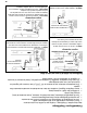
Units with Balancing Collars
Install these units with the dampers fully open and damper down the duct with the higher airflow
to equal the lower airflow. Refer to the “Balancing the Airflows” page found in this manual.
All other units require dampers for balancing airflows installed into the “Fresh Air to Building” and
“Stale Air from Building” ductwork.
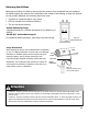
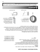
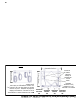
When connecting ductwork to
the collar, take note where
screws are located. Screws
should be located no further
than 1/2 in from outside edge of
collar, so as not to impede
operation of the damper.
1/2 in
Push and turn with slotted
screwdriver. Dampe
r
automatically locks when
pressure is released.
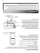
Hard/Rigid Ducting
Insulated flexible ducting
Installations where the ERV is ducted directly to the return of a furnace may require additional dampening on the
fresh air to building duct. This is due to the high return static pressures found in some furnace installations.
Attention
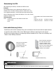
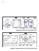
Determining the CFM
After balancing the airflows, calculate the CFM flow rate.
Example
This example shows how to determine the airflow for a 6 in
diameter duct. If the duct velocity pressure reads 0.025 in w.g.
on the digital manometer, use the chart that came with the pitot
tube to determine a duct velocity of 640 ft/min. for a duct velocity
pressure of 0.025 in w.g.
CFM Calculation
CFM = feet per minute x cross section area of duct
= 640 x 0.196
= 125
Cross section area
of some common duct
sizes:
0.087 for 4 in duct
0.196 for 6 in duct
0.139 for 5 in duct
0.267 for 7 in duct