Operation and Installation Manual Commercial Double Core Heat Recovery System Models 350DCS 350DCS-REV New Auto Dehumidistat Function prevents unwanted use of the dehumidistat when outdoor temperatures exceed 15°C (59°F). INSTALLER: Leave this manual for the homeowner Installation and wiring to be in accordance with CEC, NEC and local electrical codes. Important: Read and save these instructions.
Table of Contents CAUTION Specifications - Model 350DCS .........................................3 Before installation, careful consideration must be given to how this system will operate if connected to any other piece of mechanical equipment, i.e. a forced air furnace or air handler, operating at a higher static. After installation, the compatibility of the two pieces of equipment must be confirmed, by measuring the air flows of the HRV, by using the balancing procedure found in this manual.
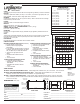
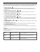
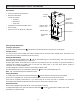
Specifications 350DCS PERFORMANCE Net supply airflow in cfm (L/s) against external static pressure CORES Two modular (two section) aluminum HRV cores arranged for high efficiency cross-flow ventilation. MOTORS Two PSC, 5 speed double shafted, 120 VAC, 3.15 A motors. (6.3 A total on high speed) with 1/10 hp at 1625 RPM. Total of 610 watts on High speed. MCA: 7.9 MOP:10 BLOWERS Centrifugal-type rated at 530 cfm (250 L/s) free air delivery.
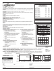
350DCS-REV Specifications PERFORMANCE Net supply airflow in cfm (L/s) against external static pressure CORES Two modular (two section) aluminum HRV cores arranged for high efficiency cross-flow ventilation. MOTORS Two PSC, 5 speed double shafted, 120 VAC, 3.15 A motors. (6.3 A total on high speed) with 1/10 hp at 1625 RPM. Total of 610 watts on High speed. MCA: 7.9 MOP:10 BLOWERS Centrifugal-type rated at 530 cfm (250 L/s) free air delivery.
Glossary STANDBY MODE - the HRV is powered/energized and waiting for fan operation to be initiated. For example, the HRV is set a Continuous Ventilation Operational Mode at Speed 0. DEFROST MODE - to ensure reliable operation during cold weather, the HRV will automatically cycle through its defrost mode as needed. DEHUMIDISTAT - a control device that senses the amount of moisture in the air and activates high speed ventilation when the air moisture level in the home exceeds the set point.
Selecting the Mode of Operation that’s Right for You The modes of operation and speeds are used to adjust your indoor ventilation rate. Experiment with the ventilation levels in your home to evaluate the ideal amount of ventilation to suit your home and personal preferences. Operational modes available to you will depend on the main control that is installed. Some features and modes may be unavailable to you. I. Continuous Ventilation This mode of operation provides continuous ventilation within the home.
Included Lifebreath Digital Control - Part #99-DXPL02 Key Features: Instruction Card 5 speed fan setting Standby setting (fan speed 0) Electronic Dehumidistat 20/40/60 HIGH speed override button Compatible with 99-DET02 Wireless Timers Easy to read backlit LCD screen Slim-line design Connect to 3 wire 20 gauge low voltage wire Five selectable modes of operation Fan Speed Button 20/40/60 High Speed Button • Continuous Ventilation • 20 min. Ventilation / 40 min.
Optional Lifebreath Ventilation Control - Part #99-BC02 Key Features: 2 speed fan setting (LOW / HIGH) Standby setting (fan OFF) Electronic Dehumidistat Compatible with 99-DET02 Wireless Timers Slim-line design Connect to 3 wire 20 gauge low voltage wire Humidity Setting Fan Speed Indicator ON/OFF Light ON/OFF Button Fan Speed Button Dehumidistat Button BC02 Operating Instructions: Turning on the Control Press and release the ON/OFF button . The light above will illuminate.
Optional Lifebreath Ventilation Control - Part #99-BC03 Key Features: Continuous LOW fan speed operation Electronic Dehumidistat 3 modes of operation: • Ventilation • Recirculation • 20/40 mode Humidity Setting 20/40 Mode Indicator Recirculation Mode Indicator Compatible with 99-DET02 Wireless Timers Slim-line design Connect to 3 wire 20 gauge low voltage wire LOW Fan Speed Indicator Light ON/OFF Button Mode Button Dehumidistat Button BC03 Operating Instructions: Turning on
Optional Lifebreath Ventilation Control - Part #99-BC04 Key Features: 2 speed fan setting (LOW / HIGH) Standby setting (fan OFF) 20/40 mode Compatible with 99-DET02 Wireless Timers Slim-line design Connect to 3 wire 20 gauge low voltage wire 20/40 Mode Indicator Light ON/OFF Light ON/OFF Button BC04 Operating Instructions: Turning on the Control Press and release the ON/OFF button above will illuminate. Fan Speed Indicator Fan Speed Button 20/40 Mode Button .
Optional Lifebreath Dehumidistat - Part #99-DH01 Key Features • The Dehumidistat measures the indoor humidity level and will initiate high speed ventilation when the moisture level in the building exceeds the set point on the control. Instruction card • Once the humidity in the building is reduced, the HRV will revert back to its previous setting. % • The Dehumidistat should be set to OFF for all season except the heating season. 80 • Connect to 3 wire 20 gauge low voltage wire.
Installation of the Main Control The Lifebreath Digital Control 99-DXPL02 is to be surface mounted onto a wall and the Lifebreath Ventilation Controls 99-BC02, 99-BC03 and 99-BC04 may either be installed onto a flush mounted electrical switch box or surface mounted onto a wall. Only one master control should be installed to a ventilation system (the face plate on this illustration may not be exactly the same as yours). 1. 2.
Installation of Optional Main Control - Part #99-DH01 ATTENTION The Lifebreath Dehumidistat may be installed onto a flush mounted 2" x 4" electrical switch box or it may be surface mounted onto a wall. Pay special attention not to damage the Contact Pins when attaching and detaching the Face Plate. (Figure B) Only 1 master control should be installed to a ventilation system (the Face Plate on this illustration may not be exactly the same as yours). Figure A - Face Plate 1.
Optional Lifebreath Wireless Timer - Part #99-DET02 The timer will override the operational mode (regardless of the settings) and initiate HIGH speed Ventilation. Upon completion of the timer cycle, the HRV will return to your selected operational mode and speed setting. ATTENTION The Wireless Timers and matched to the main wall This process is called Timers and Repeaters can wall control. Initiates HIGH speed ventilation for 20, 40 or 60 minutes.
Optional Wireless Timer - Part #99-DET02 Continued Installation of Wireless Timer 1. Separate the Face Plate from the Back Plate by firmly pulling apart (Figure A). 2. For mounting the control without a Decora plate, break off top and bottom tabs and refer to Figure C for mounting. 3. Place the Back Plate of the control in the desired location on the wall and pencil mark the top and bottom screw holes (Figure B or C). Drill two 1/8" holes. 4.
Optional Lifebreath Wireless Repeater - Part #99-RX02 Installation and Pairing of Wireless Repeaters: 99-RX02 The RX02 Repeaters are to be plugged directly into a 120V power outlet. 1. Turn on the main wall control by pressing the ON/OFF button . 2. Press the left and right buttons simultaneously on the main wall control ( and either or buttons, depending on the main control). The bottom row of 3 LED's will begin flashing. This indicates that the main control is now in pairing mode. 3.
Installation of Mechanical Timers Part # 99-101 The Mechanical timer is a 2 wire "dry contact" timer. A jumper wire must be connected between ON and RED. Connect the 2 timers wires to ON and HI. Refer to illustration. 2 wire timers require a jumper wire between ON and RED on the terminal block. Off Connect the 2 wires from the timer to ON and HI on the Terminal Block.
Operating the HRV without a Main Control and Adding Dry Contact Controls A jumper must be in place between 2 (ON) and 3 (RED) on the Terminal Block to activate the HRV for timers and/or dry contact controls. The HRV must have a Jumper in place between 2 (ON) and 3 (RED) on the Terminal Block when installing the unit without a Main Control. Adding Dry Contact Controls Low Speed - A jumper between 2 (ON) and 1 (LOW) initiates low speed ventilation.
The Ductwork System A properly designed ducting system will allow the HRV to operate at its maximum efficiency. (Air flow will be restricted by undersized ducting, use of too many elbows, tees, bends, etc.). Always try to keep duct runs as short and straight as possible. NOTE: Fully insulated ducting with an integral vapor barrier must be used on all runs passing through unheated areas in order to avoid condensation problems and energy losses from the air steams.
Stale Air Return System The stale air return system is used to draw air from the points in the building where the worst air quality problems occur. Balancing dampers and/or adjustable grilles are recommended on all return air lines which are used during installation to help balance the “draw” from different areas of the building. Alternatively, the stale air may be drawn directly from the return air duct.
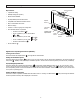
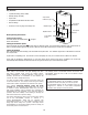
The Integrated HVAC System The HRV has become an integral component of the HVAC system. Figure A shows an HRV unit providing fresh air directly to the return air plenum of a rooftop heat/cool unit. In the balanced airflow system, the HRV exhaust removes stale room air (eg. from lunch room, storage or copy area) and returns to the space an equal amount of fresh outdoor air, making the use of an economizer obsolete in conjunction with an HRV. Many buildings have ceiling return air plenum as in Figure B.
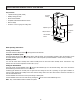
Drain Connection Drain Connection The HRV may produce some condensation during a defrost cycle. This water should flow into a nearby drain, or be taken away by a condensate pump. CAUTION The HRV and all condensate lines must be installed in a space where the temperature is maintained above the freezing point or freeze protection must be provided. DRAIN HOSE PLUMBING Pre-punched hole located in bottom center of HRV/ERV O Ring The HRV cabinet has a pre-punched hole for the drain.
Pitot Tube Air Flow Balancing - Commercial It is necessary to have balanced air flows in an HRV. The volume of air brought in from the outside must equal the volume of air exhausted by the unit.
Service and Maintenance When removing the core, the location it is removed from should be noted. The core is removed by carefully pulling the core outward from the unit, sliding it evenly along its “H channel” supports found in each corner of the core. Note the core may have some resistance when sliding out. Avoid tilting the core as this will result in its edges catching the H channel and temporarily preventing its removal.
Service and Maintenance Filters Open front service door to access the filters located in both supply and exhaust air streams. Note to remove and install filters, it may be easier to first remove the core(s). Refer to CORE. The filters are designed to stop large particles from entering in the core. The filters are fastened in place by a metal spring rod. To remove filters from core(s) simply pull the rod from one end, outward until free from core lip, and remove.
Wiring Diagram Models 350DCS and 350DCS REV 26
COMMERCIAL LIFEBREATH HEAT RECOVERY VENTILATORS ® • 2 Year Limited Warranty • 15 Year HRV Core Warranty AIRIA BRANDS INC.® (AIRIA) warrants to the original purchaser of the Commercial LIFEBREATH® model and accessories referred to below, to be free from manufacturing defects.
69-350DCS T 1-855-247-4200 F 1-800-494-4185 info@lifebreath.