
User Guide
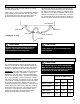
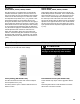


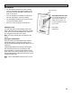
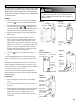
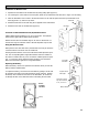
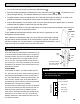
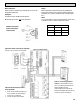

Table Of Contents

11
Drain Connections
The HRV must be level for proper drainage of conden-
sate from the drain pans.
Install a loop or "P Trap" in the condensate line and pour
a cup of water into the drain pan. This will create a wa-
ter seal which will prevent odors from being drawn up
the hose and into the fresh air supply of the HRV.
Install the drain pans in the bottom of the HRV so the
drain connections protrude through the holes provided.
Use drain hoses with hose clamps to connect the drain
pan outlets to a floor drain or standpipe. Make sure the
drain line slopes down to the outlet. If this is not possi-
ble, a condensate pump will be required for positive re-
moval of the water. Protect the drain line from freezing.
The HRV and all condensate lines must be in-
stalled in a space where the temperature is
maintained above the freezing point.
CAUTION
!
Drain trap and tubing MUST be below bottom
of door with 1/4" per foot downwards slope
away from unit.
CAUTION
!
DRAIN SPOUT
HRV Cabinet
TAPE
TO DRAIN
TEE CONNECTOR
DRAIN SPOUT
Forming the “P” Trap
Electrical Connections
Electrical Connections
It is recommended that a licensed electrician make all
electrical connections. It is very important that the unit
be properly grounded. The circuit must be sized to han-
dle the F.L.A. indicated on the name tag for the circuit.
WARNING: Verify the polarity of the power coming into
the unit with a test lamp or multimeter. Connect the
multimeter or test lamp probe to the wire being tested
and the other probe to ground. The black line should be
“live”. If the white line is “live” the polarity is reversed
and must be corrected. If both lines are live, the voltage
is not 120VAC. The black open line from the unit should
be connected to the live line and the white open line
should be connected to the neutral line. Some unit have
a safety disconnect rocker switch located just outside of
the electrical control box area. The switch disconnects
the live line. Verify that it is working properly with a
multimeter or test lamp. Always ensure the HRV is
properly grounded before and after testing.
The HRV is designed to operate with ducting.
When first starting the HRV, measure the amp
draw to each motor at each speed to ensure it
is operating at or below the max rating.
CAUTION
!
Maximum AMP Rating
HIGH MED. LOW
1200DD, 1200FD 9.4 6.0 4.5
700DD, 700FD 4.5 3.2 2.4
650DD, 650FD 4.6 3.0 2.3
455DD, 455FD 2.0 1.4 1.0