
User Guide
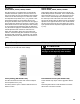


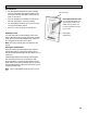
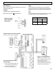

Table Of Contents

19
Function and Controls
Basic Functions
Speed control is obtained by powering 24V to one of the
designated speed taps.
Example:
A jumper between the R terminal and the
G terminal will result in
low
speed operation.
Setup
Select appropriate operational speed by installing the
jumper wire between one of the designated speed taps.
(A jumper wire is factory installed in the low speed posi-
tion.)
Note:
It is recommended to use the optional speed control Part
# 99-500 in order to obtain 3 speed fan control.
SPEED JUMPER
High
R W
Medium
R Y
Low
R G
Optional 3 Speed Control (Part #99-500)
Connect to R, W, Y and G on Thermostat
Optional 20/40/60 Minute Timer
Part# 99-DET01
Boost unit to Ventilation Mode for 20,
40, 60 minutes (no speed change).
Connect up to 4 maximum
Connect to Yellow, Red & Green
Refer to “Connecting Optional
Control” in this manual for instruc-
tions on connecting the optional Life-
breath Ventilation Control
(Part# 99-BC02) and optional Life-
breath Dehumidistat (Part# 99-DH-01)
Connect to Yellow, Red & Green
Jumper wire place-
ment on micropro-
cessor board