
User Guide
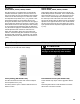


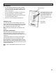
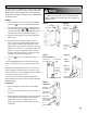
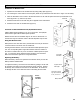
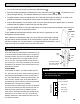
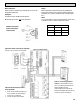

Table Of Contents

20
Connecting Optional Control - Part #99-BC02
1. Separate the Face Plate from the Back
Plate by firmly pulling apart (Figure A).
Be careful not to damage Face Plate Con-
tact Pins.
2. For mounting the control without a Deco-
ra plate, break off top and bottom tabs
and refer to Figure C for mounting.
3. Place the Back Plate of the control in the
desired location on the wall and pencil
mark the top and bottom screw holes
(Figure B or C).
4. Remove the Back Plate and mark the cen-
ter hole for the wires in the middle of the
screw holes. Refer to Figure B or C for
placement.
5. Cut in a 3/4 in by 1 in oval hole in the
wall to allow for the wire opening and
drill (two) 1/8 in holes for the screws and
wall anchors (Figure B or C).
6. Pull 3 wire 20 gauge (min.) 100 ft length
(max.), through the opening in the wall.
7. Connect red, green, and yellow to the
Wiring Terminals located on the Back
Plate (Figure B or C).
8. Attach the Back Plate to the wall using
the 2 supplied screws and anchors.
9. Attach the Face Plate to the Back Plate
(Figure A). Note: Be careful to correctly
align the Face Plate to avoid damaging
the Face Plate Contact Pins.
10. Connect the 3 wire 20 gauge (min.) 100
ft length (max.) to the digital controls
terminal strip located on the Aircom cir-
cuit board (Figure D).
The control is to be surface mounted onto a wall.
Only 1 master control should be installed to a venti-
lation system (the Face Plate on this illustration
may not be exactly the same as yours).
Pay special attention not to damage the Con-
tact Pins when attaching and detaching the
Face Plate. (Figure B)
ATTENTION
!
YEL RED
GRN
DET
Digital Controls
Terminal strip
on Aircom
circuit board
Yellow to YEL
Red to RED
Green to GRN
Use 3/20 wire
Figure A
Keep top / bottom
vent openings clear
Face Plate
Back Plate
Figure B
Figure C
1/8 in hole for
screw and
anchor
1/8 in hole for
screw and
anchor
1/8 in hole for
screw and
anchor
1/8 in hole for
screw and
anchor
1 in x 3/4 in
oval hole for
wire opening
1 in x 3/4 in
oval hole
for wire
opening
Wiring
terminals
Wiring
terminals
Wire hole
centered
between
screw holes
Break off tab
Break off tab
1”
0.75”
0.75”
1.625”
1.625”
Alternate Wall Mount
1”
Figure D