
User Guide


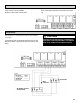
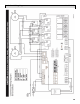
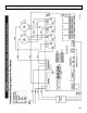
Table Of Contents

26
Reverse Installation of the HRV (Continued)
Reinstalling the Electrical Box:
21. Remove the two snap plugs from the opposite side of
the cabinet for electrical and control wires.
22. Install the two snap plugs in the cabinet holes on the
side of the HRV which electrical box was originally
removed from.
23. Route wires for both blower motors to opposite side
of HRV cabinet where electrical box is to be installed.
24. Install the grounding continuity screw in both the up-
per and lower blower assemblies on the opposite side
of the HRV where electrical box is now installed.
25. Fasten the electrical box to the cabinet of the HRV
using the 4 screws that were previously removed.
26. Remove the snap plug from the blower divider panel
and install plastic snap bushing provided in manual
bag.
27. Install snap plug in hole in blower divider panel where
lower blower motor wires were originally removed
from.
28. Route the lower blower motor wires through the hole
in the divider panel into the electrical box.
29. Route upper motor wires into the electrical box.
30. Route damper motor wires into e-box and connect the
motor wires to the circuit board, relays and capacitors
using wiring diagram found in manual for reverse in-
stallations.
31. Connect damper motor wires to circuit board using
wiring diagram found in manual for reverse installa-
tions.
32. Route thermistor wire from electrical box, through
hole in the top core support panel, and secure the
blue end to the thermistor bracket in front of the
damper motor using a plastic cable tie.
33. Connect the thermistor to the circuit board in the
electrical box.
34. Putty holes closed in blower divider panel and top
core support panel with wires protruding through.
35. Install the large single door panel on the now back of
the cabinet where electrical box was removed from
and fasten using the eight machine screws.
36. Reversing of the HRV is now complete. Continue with
the installation of the HRV.