
Indoor Air Systems Water Heater User Manual

T
he purpose of this manual is to give the contractor
guidelines for installing the LIFEBREATH Air Handler.
All national and local codes relating to this type of
equipment must be followed.
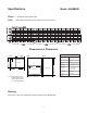
Locating The Unit
The Air Handler is designed to be installed vertically,
in a conditioned space, where the surrounding
temperature does not fall below 50°F (10°C). Attic
installations are not recommended. Typically the unit
is installed in a mechanical area of the basement, or
other partitioned mechanical room, elsewhere in the
home.
Sufficient clearance around the unit is required for
service of the filter and components. As a rule , this
unit should be installed adjacent to the hot water
heater. If this is not possible, or if the piping layout is
complex, the total head pressure on the pump should
be calculated.
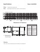
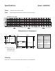
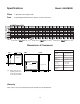
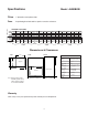
Duct Connections
To accommodate various installations, the Air
Handler has knockouts for the return air plenum on
both sides of the cabinet. Special care and attention
should be given to determining which knockouts are
to be removed.
Penetrations from sheet metal screws used to fasten
the ductwork to the cabinet of the unit should only be
placed into the duct flange provided. This is to avoid
contact and damage of the heating/air conditioning
coils and internal wiring.
Ducting
The duct sizing for the furnace section can be deter-
mined using HRAI Residential Air System Design
Manual, SMACNA, or any other industry-recognized
manuals.
Note: "Combo units" normally deliver air at approx.
110°F (43°C), and therefore may require larger than
normal ductwork. When installing the Air Handler as a
replacement unit on a retrofit application, always calcu-
late the size of duct that is there.
Any ductwork running through unconditioned space
must be sealed properly and insulated to prevent
heat loss. All local codes must be followed in deter-
mining the amount of insulation needed.
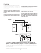
Piping
The hot water piping between the hot water tank and
the Air Handler should be new copper type, and
should not be treated with chemicals, sealant or any-
thing else, that will interfere with the purity of the
potable water. Only non-lead, low temperature solder
is permitted for sealing copper joints. The copper sol-
dered pipe size for each model is:
Model AH40DHW 1/2" nominal
AH60DHW 3/4" nominal
AH40BHW 1/2" nominal
AH60BHW 1/2" nominal
AH80BHW 1/2" nominal
Where possible the length of pipe should not exceed
200' total equivalent length. Any piping running
through unconditioned space must be insulated
toprevent heat loss, and possible freezing of the line.
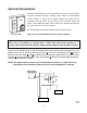
Stickers indicating direction of flow, (Supply to fur-
nace, and Return to water heater) are labeled on
the outside of the cabinet. Do not reverse these lines,
as this will cause the unit to malfunction.
For piping conventional water heaters or boilers, con-
nections to and from the Air Handler to the heater
should be made at the point where the pipes leave
the heater vertically. A "T" fitting used in each vertical
line, with the Air Handler piping connected to the hor-
izontal side of this fitting, will work best in avoiding air
locks in the circulation pump of the furnace.
*Note: Remove all shipping packaging and discard.
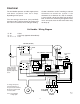
Installation
17