OPERATION, SIZING AND INSTALLATION MANUAL NOW WITH FIVE YEAR WARRANTY ON PARTS AND ACCESSORIES For Models: AH40DHW AH60DHW AH40BHW AH60BHW AH80BHW TO BE COMPLETED BY CONTRACTOR AFTER INSTALLATION Installing Contractor Telephone / Contact Serial Number Installation Date Model * LEAVE FOR HOMEOWNER NOTE: Due to ongoing research and product development, specifications, ratings and dimensions are subject to change without notice.
Table of Contents Introduction ...................................................................................................3 Description and Purpose ............................................................................4 Combo System Basic Principle ...................................................................5 Specifications ......................................................................................12 - 16 Installation .........................................................
Introduction Congratulations on your selection of the LIFEBREATH Air Handler. This is a very advanced unit that combines the outstanding efficiency and economy of the water heater/airhandler concept. With the addition of LIFEBREATH Turbulent Flow Precipitator (TFP) Air Cleaner (optional) you will have the ultimate in comfort and healthy indoor air quality. You will notice that the heated air in your home feels more comfortable than air heated by a conventional furnace.
Description and Purpose single system has the potential to increase efficiency and reduce overall capital costs. However, the proper design, installation, and commissioning of these systems is critical if these advantages are to be realized. IMPORTANT NOTE The purpose of this manual is to act as an installation guide only for the LIFEBREATH Air Handler. Manufacturers' instructions for other components, such as the waterheater/boiler, must be followed.
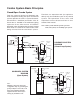
Combo System Basic Principles Closed/Open Combo System Therefore, an expansion tank (or equivalent device) may be installed as part of any closed system. The operations of the valve and expansion tank are discussed later in this section of this manual. From the aspect of delivery of domestic hot water and space heating, the Open and Closed systems operate the same. A system becomes closed when a backflow prevention valve or check valve is installed in the cold water piping upstream of the water heater.
Call for Space Heating Only Operation Air System When the thermostat calls for heat, the circulation pump is activated and hot water is drawn from the top of the water heater through the air handler, and then returned to the water heater. There should be at least a 20˚F (11˚C) temperature drop between the hot water supplied to the air handler and the returning water temperature. If the temperature drop is less then 20˚F (11˚C) two things may happen: A circulation fan draws cool house air at approx.
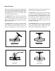
Manual Valves There are a number of manual valves required for the system to operate properly and safely. These valves are used as shut off valves, drain valves and throttling valves. They can be globe, gate, ball or balancing type valves. malfunction with age. Gate valves tend to be less expensive than the other type of valves. The globe valve can be used as a shut off, drain or throttling valve. Even in the open position, the valve is fairly restrictive to flow.
Shut Off Valves system. The drain valve should be near the low point of the return piping system upstream of the shut off valve and is preferred to be near the water heater. There are 3 shut off valves required for an integrated combo system as follows: • • • One valve (a) on the cold water side of the water heater upstream of the heating loop connection. This valve has the ability to isolate the hot water (domestic and space heating) from the household cold water supply.
Expansion Tanks Note: There are a number of pressure balancing valves and mixing valves on the market which are not certified as a anti-scalding device. Expansion tanks are only required for “Closed Systems”. The expansion tank has an air bladder, which will contract to relieve pressure in the system. Pressure is created in the closed system when water is heated in the water heater.
Water Heater Thermostat to achieve higher outputs from the furnace an anti-scald valve must be used to prevent domestic hot water temperatures above 140˚F (60˚C). The manufacturer of the Hot Water Tank should be consulted for temperatures higher than 140˚F. The water heater ther mostat is set by the installing contractor to provide the required temperature at the hot water outlet of the water heater.
Note: The vertical height of the heating loop does not impact on the head pressure as the pressure required to push the water up the vertical height is offset by the weight of the water in the vertical drop on the other side of the heating loop. With an Integrated Combo System, the hot water temperature is approx. 130˚F (54˚C) which is 60˚F (15.5˚C) above the return air temperature.
Specifications Model AH40DHW Filters 1" pleated in return plenum side. Case Prepainted galvanized steel for superior corrosion resistance. AH40DHW OUTPUT (MBH) Dimensions & Clearances 16" Top 19" Side Front Supply Air 17.25" 32.5" 22" 29.5" 14" Note: Return plenum opening available off either side of cabinet. All units conform to CSA and UL Standards AH40DHW Voltage 120 VAC 60 Hz Hp 1/3 Amps (total) 7 Water Connections 1/2" Copper Soldered Connection Airflow (High) .25 in wg .
Specifications Model AH60DHW Filters 1" pleated in return plenum side. Case Prepainted galvanized steel for superior corrosion resistance. AH60DHW OUTPUT (MBH) Dimensions & Clearances 22.25" Top 19" 17.25" Side Supply Air 32.5" 22" 29.5" 14" Blower Section Return Air 19" 29.5" Note: Return plenum opening available off either side of cabinet. All units conform to CSA and UL Standards Model AH60DHW Voltage 120 VAC 60 Hz Hp 1/2 Amps (total) 8.
Specifications Model AH40BHW Filters 1" pleated in return plenum side. Case Prepainted galvanized steel for superior corrosion resistance. Dimensions & Clearances 16" Top 19" Side Front Supply Air 17.25" 32.5" 22" 29.5" 14" Note: Return plenum opening available off either side of cabinet. All units conform to CSA and UL Standards AH40BHW Voltage 120 VAC 60 Hz Hp 1/3 Amps (total) 7 Water Connections 1/2" Copper Soldered Connection Airflow (High) .25 in wg .5 in.
Specifications Model AH60BHW Filters 1" pleated in return plenum side. Case Prepainted galvanized steel for superior corrosion resistance. Dimensions & Clearances 22.25" Top 19" 17.25" Side Supply Air 32.5" 22" 29.5" 14" Blower Section Return Air 19" 29.5" Note: Return plenum opening available off either side of cabinet. All units conform to CSA and UL Standards Model AH60BHW Voltage 120 VAC 60 Hz Hp 1/2 Amps (total) 8.
CFM @ .25" WG CFM @ .5" WG Specifications Model AH80BHW Filters 1" pleated in return plenum side. Case Prepainted galvanized steel for superior corrosion resistance. AH80BHW Output (MBH) 1639 1618 1575 1967 1868 1728 37.5 37.3 36.9 40.4 39.6 38.3 43.9 43.7 43.2 47.3 46.3 44.9 50.3 50.0 49.5 54.2 53.1 51.4 Water Temp. 130 140 150 56.8 56.5 55.8 61.1 59.9 58.1 160 63.3 62.9 62.2 68.1 66.7 64.7 170 69.7 69.3 68.6 75.1 73.6 71.3 40.7 40.4 39.9 44.1 43.1 41.6 47.6 47.2 46.7 51.6 50.5 48.
Installation The purpose of this manual is to give the contractor guidelines for installing the LIFEBREATH Air Handler. All national and local codes relating to this type of equipment must be followed. Any ductwork running through unconditioned space must be sealed properly and insulated to prevent heat loss. All local codes must be followed in determining the amount of insulation needed.
Plumbing In order to improve serviceability of our products, the check valve is included with our manual kit for field installation between the air-handler and hot water source. This will allow for ease of service to remove any installation debris or service required due to extended hard water conditions. The check valve should be installed in a vertical run of pipe with the flow of water in an upward direction. Note: Take care during soldering to avoid debris or solder from lodging in the check valve.
Electrical Caution should be used if installing a setback ther mostat to control the system. If the thermostat is set back too far, and, for example, is set to call for a lot of heat when you get out of bed, at which time showering and general water use is at its peak, then the hot water heater may not keep up. The Air Handler operates at 120V, singles phase and draws anywhere from 2-8.7 amps, depending on fan speed.
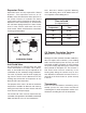
Optional Dehumidistat tat Dehumidis e to Relativ Setting s Condition Outside : WINTER at umidist . Set deh 30% to 40% , between is too dry If home ing. higher sett adjust to too humid, is ing. If home lower sett to st adju An optional dehumidistat can be connected to the furnace to help eliminate excessive moisture during the heating season. When the dehumidistat senses moisture in excess of the control setpoint, the blower will be overridden into high speed.
Start-Up Procedure In order for any appliance to work properly it must be set up and tested by a knowledgeable technician. The following conditions must be met prior to start-up 1. 2. Ensure that connecting water lines are purged and free of debris Caution: solder or other debris may cause the furnace pump or check valve to malfunction Blower wheel rotates freely inside its housing 3. Wiring connections are tight 4. All duct and pipe connections are sealed 5. Check that all packaging is removed 6.
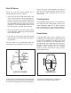
Operation Heating/Cooling Optional Circulation Timer Models When the room thermostat calls for heat from the water heater, it activates a circulation pump located inside the Air Handler. This pump delivers hot water through the furnace coil and back to the water tank/boiler. Simultaneously, the furnace blower switches on to high speed and will start circulating air across the coil, which picks up heat and delivers it to the rest of your home. Some models are equipped with a circulation timer.
Troubleshooting Lack of heat Pump is noisy 1. Check that the room thermostat is set to the desired temperature. Pumps can become noisy when air remaining in the lines interfere with their operation. If this occurs, re-purge the system as indicated in the Start-Up Procedure. 2. Confirm the units have power and the shut-off valves are open. During cooling cycle, hot water circulates through the coil 3. Ensure there is power to the unit and that the pump is working.
System Commissioning fully open This section of the manual is designed to be used with the “Commissioning of Integrated Combo System” worksheet. The worksheet is designed to guide you through the start-up process in a logical, step by step method which should minimize the work and time involved in having the system meet the designed parameters.