® CLEAN • FRESH • AIR OPERATION AND INSTALLATION MANUAL Contains ControlAir 15 For Models: 95MAX 155MAX 200MAX MAXTOP 195DCS 300DCS IMPORTANT - PLEASE READ THIS MANUAL BEFORE INSTALLING UNIT CAUTION Before installation, careful consideration must be given to how this system will operate if connected to any other piece of mechanical equipment, i.e. a forced air furnace or air handler, operating at a higher static.
INTRODUCTION Table of Contents HRV - Aluminum Core A Heat Recovery Ventilator (HRV) is designed to provide fresh air into a building while exhausting an equal amount of stale air. During the winter months, the incoming cold fresh air is warmed by utilizing the heat recovered from the stale air before it is exhausted to the outdoors.
ERV Questions & Answers What is the difference between an HRV and an ERV? and damp situation. In fact, about 2/3 of the energy used by the air conditioner system is to remove moisture. Therefore, when ventilating in the summer, less moisture brought into the home means less work for the air conditioner, and energy savings for you. The core in an HRV (Heat Recovery Ventilator) transfers heat from one air stream to the other. This is called sensible heat.
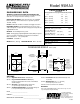
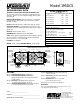
Model 95MAX PERFORMANCE ENGINEERING DATA HVI CERTIFIED Net supply airflow in cfm (L/s) against external static pressure THERMALLY CONDUCTIVE, PATENTED ALUMINUM CORE The cross-flow heat recovery core transfers heat between the two airstreams. It is easily removed for cleaning or service. E.S.P MOTORS AND BLOWERS - Each air stream has one centrifugal blower driven by a common PSC motor. 5 speed fan operation. 120 VAC, .8 Amps. FILTERS - Washable air filters in exhaust and supply air streams.
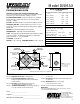
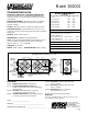
Model 155MAX PERFORMANCE ENGINEERING DATA HVI CERTIFIED Net supply airflow in cfm (L/s) against external static pressure THERMALLY CONDUCTIVE, PATENTED ALUMINUM CORE The cross-flow heat recovery core transfers heat between the two airstreams. It is easily removed for cleaning or service. E.S.P MOTORS AND BLOWERS - Each air stream has one centrifugal blower driven by a common PSC motor. 5 speed fan operation. 120 VAC, 1.0 Amps. FILTERS - Washable air filters in exhaust and supply air streams.
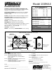
Model 200MAX ENGINEERING DATA PERFORMANCE HVI CERTIFIED THERMALLY CONDUCTIVE, PATENTED ALUMINUM CORE The cross-flow heat recovery core transfers heat between the two airstreams. It is easily removed for cleaning or service. Net supply airflow in cfm (L/s) against external static pressure E.S.P cfm L/s MOTORS AND BLOWERS - Each air stream has one centrifugal blower driven by a common PSC motor. 5 speed fan operation. 120 VAC, 1.4 Amps. FILTERS - Washable air filters in exhaust and supply air streams.
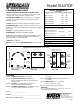
Model MAXTOP PERFORMANCE ENGINEERING DATA HVI CERTIFIED THERMALLY CONDUCTIVE, PATENTED ALUMINUM CORE The cross-flow heat recovery core transfers heat between the two airstreams. It is easily removed for cleaning or service. Net supply airflow in cfm (L/s) against external static pressure E.S.P cfm L/s @ 0.1” (25 Pa) 196 (93) MOTORS AND BLOWERS - Each air stream has one centrifugal blower driven by a common PSC motor. 5 speed fan operation. 120 VAC, 1.4 Amps. @ 0.2” (50 Pa) 188 (89) @ 0.
Model 195DCS ENGINEERING DATA PERFORMANCE HVI CERTIFIED THERMALLY CONDUCTIVE, PATENTED ALUMINUM CORE The cross-flow heat recovery core transfers heat between the two airstreams. The two cores are arranged for highly efficient counter current airflow. Net supply airflow in cfm (L/s) against external static pressure E.S.P cfm L/s @ 0.1” (25 Pa) 203 (96) @ 0.2” (50 Pa) 191 (90) @ 0.3” (75 Pa) 182 (86) @ 0.4” (100 Pa) 167 (79) FILTERS - Washable air filters in exhaust and supply air streams.
Model 300DCS ENGINEERING DATA PERFORMANCE THERMALLY CONDUCTIVE, PATENTED ALUMINUM CORE The cross-flow heat recovery core transfers heat between the two airstreams The two cores are arranged for highly efficient counter current airflow. HVI CERTIFIED Net supply airflow in cfm (L/s) against external static pressure E.S.P cfm L/s @ 0.1” (25 Pa) 265 (125) MOTORS AND BLOWERS - Each air stream has one centrifugal blower driven by a common PSC motor. 5 speed fan operation. 120 VAC, 2.9 Amps. @ 0.
® Model 200ERV CLEAN • FRESH • AIR PERFORMANCE ENGINEERING DATA Net supply airflow in cfm (L/s) against external static pressure LATENT RECOVERY/MOISTURE TRANSFER CORE The cross-flow energy recovery core transfers heat and water vapour between the two airstreams. It is easily removed for cleaning or service. E.S.P MOTORS AND BLOWERS - Each air stream has one centrifugal blower driven by a common PSC motor. 5 speed fan operation. High speed - 120 VAC, 182 Watts.
® Model 200ERVD CLEAN • FRESH • AIR ENGINEERING DATA PERFORMANCE LATENT RECOVERY/MOISTURE TRANSFER CORE The cross-flow energy recovery core transfers heat and water vapour between the two airstreams. It is easily removed for cleaning or service. Net supply airflow in cfm (L/s) against external static pressure cfm L/s @ 0.1” (25 Pa) 214 (101) MOTORS AND BLOWERS - Each air stream has one centrifugal blower driven by a common PSC motor. 5 speed fan operation. High speed - 120 VAC, 182 Watts. @ 0.
FUNCTION & CONTROL Operating the ControlAir 15 Self Test Plugging in the HRV/ERV energizes the unit. A self test function will be performed every time the HRV/ERV is energized (refer to “Self Test” for more details). After the self test has completed successfully the HRV/ERV will default to Speed 1. This is the factory default setting. Follow the instructions found on the HRV/ERV door to select desired mode and speed, or refer to the instructions found on the following page.
To select mode of operation for ControlAir 15 Press and hold the fan selection button on the Control Pad. After 5 seconds the control will begin to cycle each mode holding each for 2 seconds. Release the button when the desired mode of operation is reached. Modes of Operation LED Indication OFF No LED’s illuminated HRV/ERV is off, no controls will initiate operation. Standby / On Steady Green LED and Yellow LED to indicate speed HRV/ERV will run at speed selected in ventilation mode.
ControlAir 15 OPTIONAL REMOTE CONTROLS PROGRAMMABLE VENTILATION CONTROLLER (PVC) NEW! AIR SENTRY™ AIR QUALITY SENSOR LOCATION: Hallway, kitchen, office & work place (connect 1/unit only) • Advanced digital remote. • Digital dehumidistat. • Full fan speed control. • AIR SENTRY™ Air Quality Sensor built-in. • Recirculation mode (on compatible HRV/ERVs). • 7 day, 24 hour programmable timer. • Digital display and status lights. • 100' (30 m) maximum wire length.
USING THE DEHUMIDISTAT Some models have a built-in dehumidistat (an optional remote wall mount dehumidistat can be installed, see Optional Remote Controls), to control harmful, excess humidity during the heating season. The dehumidistat operates in % of RH (relative humidity) with 80 being high and 20 being low. The average person is comfortable between 30-45%. exceeds the set point on the control. Once the humidity in the house is reduced, the HRV/ERV will revert back to its previous setting.
DIMENSIONS 95MAX 18.5" (470 mm) Hanging straps (4) knockout for side mounting of EXHAUST return port 6" round collar converted to oval 24.5" (622 mm) inches (mm) Threaded inserts (4) at corners 18.5" (470 mm) EXHAUST Stale Air to outside 5" round collar SUPPLY Fresh air from outside 5" round collar Removably Heat Recovery Core minimum 18 inches (459 mm) required for service access Drain Pan Drain spout FRONT EXHAUST Return air from building SUPPLY Fresh air to building 6" round (conv.
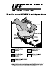
INSTALLATION Location The HRV/ERV must be located in a heated space where it will be possible to conveniently service the unit. Typically the HRV/ERV would be located in the mechanical room or an area close to the outside wall where the weatherhoods will be mounted.
INSTALLING AIR DUCTS To minimize air flow restriction, the flexible insulated duct that connects the two outside weatherhoods to the HRV/ERV should be stretched tightly and be as short as possible. A well designed and installed ducting system will allow the HRV/ERV to operate at its maximum efficiency. Always try to keep duct runs as short and straight as possible. See Installation Diagrams for various installation options. Twisting or folding the duct will severely restrict air flow.
SUPPLY AIR DUCTING Dampers and Grilles In homes without a forced air furnace, fresh air should be supplied to all bedrooms and living areas, excluding bathrooms, kitchen and utility areas. It should be supplied from high wall or ceiling locations. Grilles that diffuse the air comfortably such as the Techgrille™ are recommended. The use of balancing dampers and/or adjustable grilles to balance the flow rates into various rooms is recommended. We suggest TECHGRILLE™ air diffusers.
Installation Diagrams Example diagram only - duct configuration may change depending on model Partially Dedicated System DIRECT CONNECTION of the SUPPLY AIR STREAM to the FURNACE COLD AIR RETURN (Stale air drawn from key areas of home) EXHAUST AIR from various parts of home. i.e. bathrooms (if required), kitchens (if required). Return Air 3’ min. recommended Outdoors Cool Air Return *Unit is normally balanced on HIGH speed with furnace blower ON. NOTES: 1.
Example diagram only - duct configuration may change depending on model Simplified Installation Option 1 (Return/Return Method) Note: Option 1 is the preferred / recommended method when doing a simplified installation. RETURN AIR DIRECT CONNECTION of both the HRV/ERV SUPPLY AIR STREAM and EXHAUST AIR STREAM to the FURNACE COLD AIR RETURN 40" (1m) MINIMUM → → 3’ min. recommended Outdoors Cool Air Return Forced Air Furnace NOTES: 1.
Example diagram only - duct configuration may change depending on model Simplified Installation Option 2 (Supply/Return Method) It may be necessary to form an elbow in the supply side ducting as shown DIRECT CONNECTION of both the HRV/ERV SUPPLY AIR STREAM and EXHAUST AIR STREAM to the FURNACE COLD AIR RETURN & SUPPLY AIR SIDE RETURN AIR 3’ min. recommended 3’ min. recommended Outdoors Cool Air Return NOTES: 1. Furnace blower may be required to operate when ventilation from HRV/ERV is required.
Example diagram only - duct configuration may change depending on model Fully Dedicated System Please Note: It is the responsibility of the installer to ensure all ductwork is sized and installed as designed to ensure the system will perform as intended. All air movement devices have a performance curve. The amount of air (CFM) that an HRV/ERV will deliver is directly related to the total external static pressure (E.S.P.) of the system.
PITOT TUBE AIR FLOW BALANCING It is necessary to have balanced air flows in an HRV/ERV. The volume of air brought in from the outside must equal the volume of air exhausted by the unit.
BALANCING COLLAR INSTRUCTIONS Push and turn with slotted screwdriver. Damper automatically locks when pressure is released. When connecting ductwork to the collar, take note where screws are located. Screws should be located no further than 1/2” from outside edge of collar, so as not to impede operation of the damper.
Maintenance Routine for HRV (for ERV, see following page) 1. Inspect Exterior Hoods at least once a month. 6. Clean Duct Work if Required Make sure exhaust and fresh air supply hoods are not blocked or restricted by leaves, grass, or snow. In winter, it is especially important to make sure snow is not blocking the hoods or that frost has not built up on the wire mesh (bird screen). The duct work running to and from the HRV may accumulate dirt. Wipe and vacuum the duct once every year.
Maintenance Routine for ERV (for HRV, see previous page) 1. Inspect Exterior Hoods at least once a month 5. Clean Duct Work if Required Make sure exhaust and fresh air supply hoods are not blocked up or restricted by leaves, grass, or dirt. WARNING: Blockage of hoods may cause an imbalance. The duct work running to and from the ERV may accumulate dirt. Wipe and vacuum the duct once every year. You may wish to contact a Heating/Ventilation company to do this. 2. Clean Air Filters Four Times a Year 6.
TROUBLESHOOTING YOUR HRV/ERV SYSTEM SYMPTOM CAUSE SOLUTION Poor Air Flows • 1/4” (6 mm) mesh on the outside hoods is plugged • filters plugged • core obstructed • house grilles closed or blocked • dampers are closed if installed • poor power supply at site • ductwork is restricting HRV/ERV • improper speed control setting • HRV/ERV airflow improperly balanced • clean exterior hoods or vents • remove and clean filter • remove and clean core • check and open grilles • open and adjust dampers • have elec
Technical Bulletin When using the ControlAir 15 relay contacts to initiate blower operation on a furnace, certain thermostats will initiate the outdoor cooling condenser when R and G are closed. Use this wiring configuration to stop the ControlAir15 relay contacts from initializing the condenser unit. This problem can occur at the thermostat because the Y terminal is connected to the G terminal internal to the stat.
RESIDENTIAL WIRING DIAGRAM MICRO PROCESSOR BOARD P4 TO DISABLE RECIRCULATION REMOVE SEL2 THERMIST0R P2 INTERNAL DEHUMIDISTAT SEL2 Note: All control connections are labeled by colour. Connect to corresponding colour with low voltage wire ( 20 gauge minimum). YEL P5 REMOVE SEL1 FOR R-2000 GRN SEL1 DRY CONTACT WARNING 750 ma MAX FUSE ORN T1 N/C RED T2 COMMON BLK T6 N/O SEE DEFROST DETAIL P1 LINE A dry contact closure between red & black will initiate high speed override.
511 McCormick Blvd. London, Ontario N5W 4C Ph: (519) 457-1904 Fx: (519) 457-1676 Email: nutech@lifebreath.co Website: www.lifebreath.