RNC4-TPD/TPF INSTALLATION GUIDE 69-RNC4-INSTALL 072717 511 McCormick Blvd. London, ON Canada N5W 4C8 General Info/Tech Support: 1 855. 247 4200 Online: www.lifebreath.
Table of Contents Location ...................................................................................................................................... 2 Pre-Installation Notes ................................................................................................................... 3 Simplified Installation (Return/Return Method) ................................................................................ 4 Partially Dedicated System ..................................................
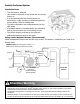
Pre-Installation Notes Read this notice before installing unit: Note Due to ongoing research and product development, specifications, ratings, and dimensions are subject to change without notice. Refer to www.LIFEBREATH.com for the latest product information. Attention Do not apply electrical power to the unit until after the completion of the installation (including installation of low voltage control wiring).
Simplified Installation (Return/Return Method) Installation Notes The HRV must be balanced. Unit should be balanced on high speed with the furnace blower on. It is mandatory that the furnace blower run continuously or HRV operation be interlocked with the furnace blower. The duct configuration may change depending on the HRV model. A backdraft damper is recommended in the exhaust air duct to prevent outdoor air from entering the unit.
Partially Dedicated System Installation Notes The HRV must be balanced. Unit should be balanced on high speed with the furnace blower on. It is recommended that the furnace blower run continuously or HRV operation be interlocked with the furnace blower. Refer to building code. The duct configuration may change depending on the HRV model. A backdraft damper is recommended in the exhaust air duct to prevent outdoor air from entering the unit.
Fully Dedicated System Installation Notes The HRV must be balanced. When balancing, all external exhaust systems should be turned off (i.e. range hood, dryer exhaust, bathroom vents). All exhausting appliances should have their own make-up air, as this is not an intended use of the HRV system. The duct configuration may change depending on the HRV model. The airflow must be confirmed on site using the balancing procedures found in this guide.
Mounting the RNC4-TPD and RNC4-TPF Units: 1. Begin by locating the four mounting tabs on the left and right sides of the unit, at the front and back. 2. Using a flat / slot screwdriver, bend out the four tabs to approximately 45o. Four Mounting Points 3. Once the tabs have been all bent outwards, insert the "S" hooks through the four holes on the tabs. 4. Continue with mounting the HRV using the instructions found on page 8.
Hanging Straps - Installation Notes Use 4 screws and 4 washers (not provided) to attach the hanging straps to the floor joists. The washer must be wider than the eyelet of the grommet on the hanging strap. The hanging straps are designed to reduce the possibility of noise, resonance and harmonics. Step 1: Insert the screws and washers (not included) through the hanging strap grommets and fasten to the joists. Figure A Joist Step 3: Hook the bottom grommets of the straps through the “S” hooks.
Drain Connection Installation Notes The HRV cabinet has pre-punched holes for the drain (see below). The HRV may produce some condensation during a defrost cycle. This water should flow into a nearby drain, or be taken away by a condensate pump. 1. Ensure that the drain spout has a foam gasket on the bottom of the head. See figure below. 2. Insert the drain spout through the hole in the drain pan. 3. HAND TIGHTEN the nylon nut which will hold the drain spout in place. 4.
Grilles Adjustable grilles should be used to balance the flow rates into and out of various rooms. The grilles should not be adjusted after balancing the unit. Grilles or diffusers should be positioned high on the wall or in the ceiling. Kitchen exhaust should never be connected to the range hood. They should be installed at least 4 ft (1.2 m) horizontally away from the stove.
Grille Fittings Stack Head Elbow (part # 99-WF4 / 99WF6) Quick Mount Fitting Use this rough-in fitting before the drywall is installed. This fitting is ideal for running ducting through 2 x 4 (min.) studded walls. Nail to stud. Available sizes are 4 in and 6 in. (part # 99-QM6) Use this rough-in fitting before the drywall is Installed. Nail fitting onto the stud. Available size: 6 in.
Lifebreath Weatherhood Fixed covered weatherhoods have a built-in bird screen with a 1/4 in (6 mm) mesh to prevent foreign objects from entering the ductwork. Installation Notes The inner and outer liners of the flexible insulated duct must be clamped to the sleeve of the weatherhoods (as close to the outside as possible) and the appropriate port on the HRV. It is very important that the fresh air intake line be given special attention to make sure it is well sealed.
Dual Hood Part 99-194 With the Lifebreath Dual Hood, only one 6 in hole is required in the exterior wall to complete two connections: fresh air intake and stale air exhaust. Side View 25" 21.5" SideView of Hood and Backplate 8.25" 6" 4" 6" Stale Air Exhaust Top View 8.
Main Control Installation The Lifebreath Digital Control 99-DXPL02 is to be surface mounted onto a wall and the Lifebreath Ventilation Controls 99-BC02, 99-BC03 and 99-BC04 may either be installed onto a flush mounted electrical switch box or surface mounted onto a wall. Only one master control should be installed to a ventilation system (the face plate on this illustration may not be exactly the same as yours).
Mechanical Timers Installation 99-101 The Mechanical Timer is a 2 wire “dry contact” timer. A jumper wire must be connected between 2 (ON) and 3 (RED). Connect the 2 timer wires to ON and HI. 2 wire timers require a jumper wire between ON and RED on the terminal block Connect the 2 wires from the timer to ON and HI on the terminal block.
Installation and Operation of Wireless 20/40/60 Minute Timer: 99-DET02 The Timers may be installed onto a flush mounted electrical switch box or it may be surface mounted onto a wall. Multiple Timers may be installed in a ventilation system. To increase the range of a wireless Timer, a RX02 Repeater should be used. Pairing: 1. Turn on the main wall control by pressing the ON/OFF button and remove the battery from Timer. 2.
Installation and Pairing of Repeaters: 99-RX02 The RX02 Repeaters are to be plugged directly into a 120V power outlet 1. Turn on the main wall control by pressing the ON/OFF button . 2. RX02 with DXPL02 Controls: Press the left and right buttons simultaneously on the main wall control ( and RESET buttons). The screen will go blank and the wireless symbol will appear flashing on the bottom right of the display. This indicates that the main control is now in pairing mode.
Installation and Operation 20/40/60 Minute Timer: 99-DET01 Operating your Lifebreath 20/40/60 Minute Fan Timer Status Lights Press and release the Select Button to activate a 20, 40 or 60 minute high speed override cycle. The Light will illuminate and the unit will run on high speed ventilation for the selected time. The Light will dim after 10 sec. for run time. The Light will flash during the last 5 min. of the cycle.
Dimensional Drawing for RNC4-TPF Model Fresh Air To Inside Note: Front clearance of 25 in (635 mm) is recommended for servicing unit. All ducts use 4 in (102 mm) round collars, balancing dampers are located in all air streams.
Balancing the Airflows Balancing the airflows is critical to ensuring that the amount of air introduced from the outside of the building equals the amount of air exhausted to the outside of the building. If these two airflows are not properly balanced, the following issues may occur: A positive or negative pressure in the house HRV not operate at its maximum efficiency The unit not defrost properly Airflow Measuring Gauge A digital manometer is a suitable instrument for the balancing of airflows.
Determining the CFM After balancing the airflows, calculate the CFM flow rate. Example This example shows how to determine the airflow for a 6 in diameter duct. If the duct velocity pressure reads 0.025 in w.g. on the digital manometer, use the chart that came with the pitot tube to determine a duct velocity of 640 ft/min. for a duct velocity pressure of 0.025 in w.g. Cross section area of some common duct CFM Calculation sizes: CFM = feet per minute x cross section area of duct 0.139 for 5 in duct 0.
Balancing Preparation Prior to performing the air balancing procedure, perform the following steps: Seal the ductwork. Confirm the installation and proper operation of all the components of the HRV. Fully open the balancing dampers. Turn off all household exhaust devices (range hood, clothes dryer, bathroom fans). Set the HRV at high speed. Prior to balancing the unit, first adjust airflows in the branch lines to specific areas of the house.
Balancing the Airflow using the Door Ports Door balancing ports (not on all models) are designed to be used in the conjunction with a digital manometer to measure the stale and fresh airflows for balancing. Step 1: Prepare the airflow measuring device (i.e. magnehelic gauge or digital manometer) by connecting the hoses to the low and high pressure side of the gauge.
Airflow Reference Charts RNC4-TPD Model RNC4-TPDmodels have 3 airflow charts for their installer adjustable high speed settings. Refer to “Installer Selectable High Speed Settings” in this manual for instructions on how to adjust the circuit board DIP switches. Hi 3 Pressure Drop ("w.g.) (Pa) 0.400 100 0.410 103 0.420 105 0.430 108 0.440 110 0.450 113 0.460 115 0.470 118 0.480 120 0.490 123 0.500 125 0.510 128 0.520 130 0.530 133 0.540 135 0.550 138 0.560 140 0.570 143 0.580 145 0.590 148 0.600 150 0.
Airflow Reference Charts RNC4-TPF Model RNC4-TPF models have 3 airflow charts for their installer adjustable high speed settings. Refer to “Installer Selectable High Speed Settings” in this manual for instructions on how to adjust the circuit board DIP switches. Hi 3 Pressure Drop ("w.g.) (Pa) 0.300 75 0.310 78 0.320 80 0.330 83 0.340 85 0.350 88 0.360 90 0.370 93 0.380 95 0.390 98 0.400 100 0.410 103 0.420 105 0.430 108 0.440 110 0.450 113 0.460 115 0.470 118 0.480 120 0.490 123 0.500 125 0.510 128 0.
Troubleshooting SYMPTOM Poor airflows CAUSE Supply air feels cold 1/4 in (6 mm) mesh on outside hood is plugged Filters plugged Core obstructed House grills closed or blocked Dampers are closed if installed Poor power supply at site Ductwork is restricting HRV Improper speed control setting HRV airflow improperly balanced SOLUTION Poor location of supply grilles, the airflow may irritate the occupant Outdoor temperature extremely cold Dehumidistat in no
Dépannage SYMPTÔME Débit d'air médiocre CAUSE le treillis de 1/4 po (6 mm) sur les capuchons extérieurs est bouché filtres bouchés noyau obstrué grilles dans la maison fermées ou bloquées les registres, s'ils ont été posés, sont fermés mauvaise alimentation électrique sur les lieux SOLUTION nettoyez les évents ou capuchons extérieurs retirez et nettoyez le filtre retirez et nettoyez le noyau vérifiez et ouvrez les grilles ouvrez et ajustez les registres demandez à un élect
Tableau de référence des débits d'air pour les modèles RNC4-TPF On a préparé trois tableaux de débits d'air couvrant les modèles RNC4-TPF afin de tenir compte de leurs réglages de haute vitesse que l'installateur pourra choisir. Haute 3 Baisse de Pression (po c.e.) (Pa) 0.300 0.310 0.320 0.330 0.340 0.350 0.360 0.370 0.380 0.390 0.400 0.410 0.420 0.430 0.440 0.450 0.460 0.470 0.480 0.490 0.500 0.510 0.520 0.530 0.540 0.550 0.560 0.570 0.580 0.590 0.600 0.610 0.620 0.630 0.640 0.650 0.660 0.670 0.680 0.
Tableau de référence des débits d'air pour les modèles RNC4-TPD On a préparé trois tableaux de débits d'air couvrant les modèles RNC4-TPD afin de tenir compte de leurs réglages de haute vitesse que l'installateur pourra choisir. Haute 3 Baisse de Pression (po c.e.) (Pa) 0.400 0.410 0.420 0.430 0.440 0.450 0.460 0.470 0.480 0.490 0.500 0.510 0.520 0.530 0.540 0.550 0.560 0.570 0.580 0.590 0.600 0.610 0.620 0.630 0.640 0.650 0.660 0.670 0.680 0.690 0.700 0.710 0.720 0.730 0.740 0.750 0.760 0.770 0.780 0.
Équilibrage des circuits d'air en utilisant les orifices dans la porte Les orifices d'équilibrage dans la porte (qu'on ne trouve pas sur tous les modèles) peuvent être utilisés, de concert avec un manomètre numérique, pour mesurer les débits d'air vicié et d'air neuf dans le but de les équilibrer.
Préparatifs pour l'équilibrage Avant de procéder à l'équilibrage, n'oubliez pas de vérifier les points suivants : • Tout le réseau de conduits doit avoir été complètement scellé. • Tous les composants du VRC doivent être en place et en bon état de marche. • Les registres d'équilibrage doivent être complètements ouverts. • Tous les dispositifs d'évacuation (hotte de cuisinière, sécheuse, évents de salles de bains) doivent être arrêtés. • Le VRC doit être réglé à sa haute vitesse.
Comment déterminer le débit d'air en pcm Après avoir achevé l'équilibrage, calculez le débit d'air en pieds cubes/ minute. Exemple Voici un exemple dans lequel on détermine le débit d'air dans un conduit de 6 pouces. Servez-vous du tableau fourni avec le tube de Pitot pour déterminer une vélocité dans le conduit de 640 pieds/minute pour une pression due à la vitesse de 0.025 po (colonne d'eau). Calcul des pieds cubes/minute (pcm) pcm = pieds par minute x surface transversale du conduit = 640 x 0.
Équilibrage des débits d'air L'équilibrage des circuits d'air est essentiel pour que la quantité d'air provenant de l'extérieur de l'édifice soit égale à la quantité évacuée par l'appareil.
Dessin dimensionnel pour le modèle RNC4-TPF Air neuf vers l’intérieur Air vicié vers l’extérieur 18 3/4" (476 mm) Air vicié de l’intérieur Devant 19 1/4" (489 mm) Air neuf de l’extérieur 17 7/8" (454 mm) Dessus Dessin dimensionnel pour le modèle RNC4-TPD Air neuf vers l’intérieur Air vicié vers l’extérieur 18 3/4" (476 mm) Air vicié de l’intérieur 19 1/4" (489 mm) Devant Air neuf de l’extérieur 17 7/8" (454 mm) Dessus 19
Installation et utilisation de la minuterie pour 20/40/60 minutes 99-DET01 Voyant de Utilisation de votre minuterie à 20/40/60 minutes pour le ventilateur rotatif haute vitesse Enfoncez et relâchez le bouton sélecteur pour commencer un cycle prioritaire de 20, 40 ou 60 minutes à haute vitesse. Le voyant de haute vitesse s'allume et l'appareil fournit une ventila-tion à grande vitesse pendant la période prévue. Le voyant de haute vitesse se met en veil-leuse après 10 secondes de marche.
Installation et pairage de répéteurs 99-RX02 Les répéteurs RX02 doivent être branchés dans une prise de courant de 120 V. Une fois que les répéteurs ont été appariés avec succès, appuyez sur le bouton principale pour quitter le mode de pairage. 5. Branchez le répéteur RX02 dans la prise de courant. Après environ 12 secondes, la DEL verte clignote puis demeure allumée, ce qui indique que le répéteur est apparié avec la commande principale. Un témoin rouge signifie que le pairage n'est pas réussi. 4.
Installation et fonctionnement de la minuterie sans fil 20/40/60 minutes 99-DET02 Les minuteries peut être installée sur une boîte électrique encastrée ou bien on peut la monter en surface sur un mur. On peut aussi accroître la portée d'une minuterie sans fil au moyen d’un répéteur RX02. Pairage 1. Mettez la commande murale principale en marche en appuyant sur le bouton de marche/arrêt et retirez la pile de la minuterie. 2.
Installation de la minuterie mécanique 99-101 La minuterie mécanique est une minuterie à “contacts secs” à deux fils. On doit connecter un cavalier entre la borne de marche 2 (ON) et la borne rouge 3 (RED). Connectez les deux fils de la minuterie aux bornes ON et HI. La minuterie à deux fils exigent un cavalier entre la borne de marche (ON) et la borne rouge (RED) sur la plaque de connexions. Connectez les deux fils provenant de la minuterie aux bornes ON et HI sur le bloc de connexions.
Installation de la commande principale La commande numérique Lifebreath 99-DXPL02 se monte en saillie à la surface d’un mur; les commandes de ventilation Lifebreath 99-BC02, 99-BC03 et 99-BC04 peuvent être installées en saillie aussi bien sur un mur que sur une boîte de jonction affleurante. On ne devrait installer qu'une (1) seule commande principale pour un même système de ventilation. (Il se pourrait que la plaque avant illustrée sur cette page ne soit pas absolument identique à la vôtre).
Capuchon double Pièce Nº 99-194 Avec le capuchon double Lifebreath, il suffit de percer un seul trou de 6 pouces dans le mur extérieur pour effectuer deux raccordements, un pour l'arrivée de l'air neuf et l'autre pour l'évacuation de l'air vicié. Vue de côté 25po 21.5po 8.25po Vue de côté de capuchon et plaque arrière 4po 6po 6po Vue par-dessus 8.
Capuchons anti-intempéries Lifebreath Les capuchons anti-intempéries couverts fixes incorporent un grillage anti-oiseaux à mailles de 1/4 po (6 mm) pour empêcher des objets étrangers de pénétrer dans la canalisation. Remarques concernant l'installation Les revêtements intérieur et extérieur de la gaine flexible isolée doivent être solidement attachés au manchon des capuchons anti-intempéries (aussi près que possible du dehors) et à l'orifice approprié sur le VRC.
Raccords pour les grilles Raccord à montage rapide (Pièce Nº 99-QM6) Utilisez ce raccord avant la pose du revêtement mural intérieur. • Clouez le raccord sur le montant. • Disponible en diamètre de 6 pouces. Coude pour sommet de canalisation (Pièce Nº 99-WF6) Utilisez ce raccord avant la pose du revêtement mural intérieur. Ce raccord est idéal pour acheminer la canalisation à travers un mur à montants de 2 po x 4 po (minimum). • Clouez le raccord sur un montant. • Disponible en diamètre de 6 pouces.
Grilles On conseille d'utiliser des grilles réglables pour équilibrer les débits d'air dans les diverses pièces de la maison. Ces grilles ne devraient pas être ajustées après qu'on a procédé à l'équilibrage de l'appareil. Les grilles ou les diffuseurs devraient être montés en hauteur sur le mur ou dans le plafond. Les grilles d'évacuation de la cuisine ne doivent jamais être raccordées à la hotte d'une cuisinière.
Tuyau d'égouttement Directives d’installation Le fonctionnement du VRC peut entraîner la formation de condensation. Cette eau doit être évacuée par raccordement indirect jusqu’à un avaloir proche ou au moyen d'une pompe de relevage de condensat. Le coffre du VRC est pourvu de trous prépercés pour l’évacuation (voir ci-dessous). 1. Vérifiez si les goulottes d’égouttement sont pourvues d’un joint en mousse sur leur face inférieure, tel qu’illustré plus bas. 2.
Bandes de suspension Remarques concernant l'installation Utilisez quatre vis et quatre rondelles (non fournies) pour fixer les bandes de suspension aux solives du plancher. On doit vérifier que les rondelles sont plus larges que les oeillets des viroles des bandes de suspension. Ces bandes de suspension ont été conçues pour diminuer la possibilité de bruit, de résonance ou d'harmoniques.
Montage du RNC4-TPD / RNC4-TPD 1. Commencez par localiser les 4 languettes de montage sur les côtés gauche et droit de l'appareil, à l'avant et à l'arrière. 2. À l'aide d'un tournevis plat, inclinez les 4 languettes à environ 45o vers l'extérieur. 4 Points De Suspension 3. Une fois les languettes inclinées, insérez les crochets en S dans les trous des 4 languettes. 4. Continuez avec le montage du VRC selon les directives de la page 8.
Système entièrement spécifique Remarques concernant l'installation • • • • • Le VRC doit être équilibré. Durant l'équilibrage, tous les systèmes d'évacuation externes doivent être arrêtés (OFF). Cela s'applique à la cuisinière, à l'évacuation de la sécheuse, aux évents des salles de bains, etc. Tous les appareils à évacuation devraient obtenir leur propre air d'appoint, car il ne s'agit pas là d'une fonction prévue pour le VRC. La configuration des conduits pourrait différer selon le modèle de VRC.
Système partiellement spécifique Remarques concernant l'installation Le VRC doit être équilibré. • L'appareil devrait être équilibré à haute vitesse, alors que la soufflante de l'appareil de chauffage (fournaise) est en marche (ON). • Il est recommandé que la soufflante de l'appareil de chauffage (fournaise) marche sans interruption ou que le fonctionnement du VRC soit synchronisé avec celui de la soufflante.
Installation simplifiée (méthode reprise/reprise) Remarques concernant l'installation • Le VRC doit être équilibré. • L'appareil devrait être équilibré à haute vitesse, alors que la soufflante de l'appareil de chauffage (fournaise) est en marche (ON). • Il est essentiel que la soufflante de l'appareil de chauffage (fournaise) marche sans interruption ou que le fonctionnement du VRC soit synchronisé avec celui de la soufflante. • La configuration des conduits pourrait différer selon le modèle de VRC.
Conseils avant l'installation Lisez attentivement ce qui suit avant de commencer l'installation : Remarque • À cause de notre programme continu de recherches et de perfectionnement des produits, les caractéristiques, les puissances nominales et les dimensions peuvent être modifiées sans préavis. Consultez le www.LIFEBREATH.com pour les toutes dernières informations sur nos produits.
Table des matières Emplacement ................................................................................................................................ 2 Conseils avant l'installation ............................................................................................................ 3 Installation simplifiée (méthode reprise/reprise) .............................................................................. 4 Système partiellement spécifique .............................................
RNC4 TPD/TPF GUIDE D’INSTALLATION 69-RNC4-INSTALL 072717 511 boul. McCormick. London, ON Canada N5W 4C8 Information générale / support technique: 1 855. 247 4200 En ligne: www.lifebreath.