
Operation Manual


12
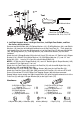
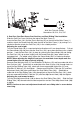
2. Front Post and Tension Control Knob Installation
Remove six M8x15 Bolts (38), Ø8 Spring Washers (41), and Ø20xØ8 Big Curve Washers
(11) from the Main Frame (1).
Insert the Tension Cable (27) through into the bottom hole of Front Post (5) and pull it out
from the square hole of Front Post (5).
Connect the Sensor Wire II (65) from the Main Frame (1) to the Sensor Wire I (64) from the
Front Post (5).
Insert the Front Post (5) onto the tube of the Main Frame (1) and secure with six M8x15 Bolts
(38), Ø8 Spring Washers (41), and Ø20xØ8 Big Curve Washers (11) that were removed.
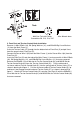
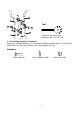
Remove the Ø20xØ5.2 Curve Washer for Tension Control Knob (61) and M5x55 Bolt for
Tension Control Knob (62) from the Tension Control Knob (51). Put the cable end of
resistance cable of Tension Control Knob (51) into the spring hook of Tension Cable (27) as
shown in drawing A of figure 2. Pull the resistance cable of Tension Control Knob (51) up
and force it into the gap of metal bracket of Tension Cable (27) as shown in drawing B of
figure 2. Attach the Tension Control Knob (51) onto the Front Post (5) with the Ø20xØ5.2
Curve Washer for Tension Control Knob (61) and M5x55 Bolt for Tension Control Knob (62)
that were removed.
Multi Hex Tool with Phillips
Screwdriver S8, S13, S14, S15
Allen Wrench 6mm
Tool:
41
41
38
11
27
65
61
62
51
64
38
11
5
1
27
27
27
51
51
A B