CLASSIC II, MAGNETIC RECUMBENT BIKE ITEM NO: 26260 OWNER’S MANUAL IMPORTANT: Read all instructions carefully before using this product. owner’s manual for future reference. Retain this The specifications of this product may vary from this photo, subject to change without notice.
TABLE OF CONTENTS WARRANTY ------------------------------------------------------------------------------- 2 IMPORTANT SAFETY INSTRUCTIONS ------------------------------------------- 3 PARTS LIST ------------------------------------------------------------------------------- 4 HARDWARE PACKING LIST --------------------------------------------------------- 5 TOOLS -------------------------------------------------------------------------------------- 6 OVERVIEW DRAWING ----------------------------------------
ONE YEAR LIMITED WARRANTY LifeGear Inc. warrants to the original purchaser that this product is free from defects in material and workmanship when used for the purpose intended, under the conditions that it has been installed and operated in accordance with LifeGear's Owner's Manual. LifeGear's obligation under this warranty is limited to replacing or repairing free of charge, any parts which may prove to be defective under normal home use.
IMPORTANT SAFETY INSTRUCTIONS Basic precautions should always be followed, including the following important safety instructions when using this equipment: Read all instructions before using this equipment. 1. Read all instructions and follow it carefully before using this equipment. Make sure the equipment is properly assembled and tightened before use. 2. Before exercise, in order to avoid injuring the muscle, warm-up exercise is necessary. Refer to the Warm Up and Cool Down Routine pages.
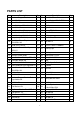
PARTS LIST No. Description Qty No. Description Qty 001 Backrest Support Bracket 1 030 Bolt M10x57 4 002 Front Stabilizer 1 031 Curve Washer Ø10.5xØ25x2 4 003 Rear Main Frame 1 032 Cap Nut M10 4 004 Rear Stabilizer Ø50x1.5x430 1 033 Left Cover 1 005 Front Main Frame 1 034 Right Cover 1 006 Front Handlebar Post 1 035 Screw ST4.
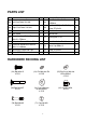
PARTS LIST No. Description Qty No. Description Qty 059 Left Foot Pedal YH-30X 1 068 Hand Pulse Sensor Wire L=650mm 2 060 Right Foot Pedal YH-30X 1 069 Pan Head Phillips Self Drilling Screw ST4.2x20 4 061 Sensor with Wire L=500mm 1 070 Bolt M8x45 2 062 Belt 330J6 1 071 Cap Nut M8 4 2 072 Bearing Nut II 7/8" 1 1 073 Front Handlebar Post Cover 1 2 074 Cover Cap Ø50x1.2 2 066 Rear Main Frame End Cap 1 075 Screw ST4.2x25 7 067 Screw ST2.
TOOLS Allen Wrench S6 1 PC Multi Hex Tool with Phillips Screwdriver S10, S13, S14, S15 1 PC Multi Hex Tool 1 PC 6
69 74 69 34 18 7 16 28 53 48 61 28 31 61 41 67 42 16 72 29 26 30 2 44 56 58 23 57 54 63 47 53 76 40 24 25 14 12 19 6 39 64 18 32 65 5 55 20 12 60 37 50 51 42 19 41 43 45 17 38 36 24 76 64 73 49 63 9 46 52 23 59 66 7 22 8 33 3 69 62 24 71 1 58 24 75 21 71 74 69 75 65 32 31 27 71 58 15 4 10 21 12 22 30 12 35 11 10 68 27 25 70 15 11 35 13 OVERVIEW DRAWING
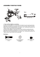
ASSEMBLY INSTRUCTIONS 61 65 5 3 32 31 Tool: 4 2 32 31 Multi Hex Tool 30 30 1. Front and Rear Stabilizers Installation Position the Front Stabilizer (2) in front of the Front Main Frame (5) and align bolt holes. Attach the Front Stabilizer (2) onto the front curve of the Front Main Frame (5) with two M10x57 Bolts (30), two Ø10.5xØ25x2 Curve Washers (31), and two M10 Cap Nuts (32). Tighten cap nuts with the Multi Hex Tool provided.
14 6 A B 40 24 76 63 64 61 60 38 36 Tool: 14 24 25 23 14 40 40 76 73 40 65 Allen Wrench S6 5 46 Multi Hex Tool with Phillips Screwdriver S10, S13, S14, S15 59 2. Front Handlebar Post, Tension Control Knob, and Foot Pedals Installation Remove one M8x15 Bolt (23), one Ø8.4xØ25x2 Big Curve Washer (25), four Ø8 Flat Washers (24), and four M8x10 Bolts (76) from the tube of the Front Main Frame (5). Remove bolts with the S6 Allen Wrench provided.
“L” for Left. Insert the pedal shaft of Left Foot Pedal (59) into threaded hole in the left Crank (46). Turn the pedal shaft by hand in the counter-clockwise direction until snug. Note: DO NOT turn the pedal shaft in the clockwise direction, doing so will strip the threads. Tighten the pedal shaft of Left Foot Pedal (59) with the Multi Hex Tool with Phillips Screwdriver provided. Insert pedal shaft of Right Foot Pedal (60) into threaded hole in right Crank (46).
1 Tool: 71 24 71 13 71 24 23 65 24 23 3 Allen Wrench S6 68 25 70 Multi Hex Tool with Phillips Screwdriver S10, S13, S14, S15 3. Backrest Support Bracket and Handlebar Installation Attach the Backrest Support Bracket (1) onto the Rear Main Frame (3) with four M8x15 Bolts (23), four Ø8 Flat Washers (24), and two M8 Cap Nuts (71). Tighten bolts and cap nut with the S6 Allen Wrench and Multi Hex Tool with Phillips Screwdriver provided.
9 63 Tool: 64 13 39 Multi Hex Tool with Phillips Screwdriver S10, S13, S14, S15 6 4. Computer Installation Remove four M5x12 Bolts (39) from the back of the Computer (9). Remove bolts with the Multi Hex Tool with Phillips Screwdriver provided. Connect the Extension Hand Pulse Sensor Wires II (63) and Extension Sensor Wire (64) to the wires that come from the Computer (9). Tuck wires into the Front Handlebar Post (6).
1 8 7 58 21 58 21 Tool: Multi Hex Tool with Phillips Screwdriver S10, S13, S14, S15 3 5. Seat and Back Cushions Installation Remove eight M6x15 Bolts (21) and eight Ø6 Flat Washers (58) from the back of the Seat and Back Cushions (7, 8). Remove bolts with the Multi Hex Tool with Phillips Screwdriver provided. Then attach the Seat and Back Cushions (7, 8) onto the Backrest Support Bracket (1) with eight M6x15 Bolts (21) and eight Ø6 Flat Washers (58) that were removed.
OPERATING THE COMPUTER USING YOUR COMPUTER The computer can be activated by pressing the buttons or by pedaling. If you leave the equipment for 4 minutes, the power will turn off automatically. BUTTON FUNCTIONS: MODE: Press the MODE button to select each function of the computer. Press and hold the MODE button for 4 seconds to reset all data values to zero except the ODO (ODOMETER) data values.
ADJUSTMENTS Adjusting the Tension Control Knob To increase the load, turn the tension control knob in a clockwise direction. To decrease the load, turn the tension control knob in a counterclockwise direction. Tension Control Knob Adjusting the Rear Stabilizer End Cap Turn the rear stabilizer end cap on the rear stabilizer as needed to level the recumbent bike. Rear Stabilizer End Cap Adjusting the Seat Forth or Back Turn the round knob in a counterclockwise direction until it can be pulled out.
MAINTENANCE Cleaning The recumbent bike can be cleaned with a soft cloth and mild detergent. Do not use abrasives or solvents on plastic parts. Please wipe your perspiration off the recumbent bike after each use. Be careful not get excessive moisture on the computer display panel as this might cause an electrical hazard or electronics to fail. Please keep the recumbent bike, specially, the computer console, out of direct sunlight to prevent screen damage.
WARM UP AND COOL DOWN ROUTINE The WARM-UP is an important part of any workout. The purpose of warming up is to prepare your body for exercise and to minimize injuries. Warm up for two to five minutes before aerobic exercising. It should begin every session to prepare your body for more strenuous exercise by heating up and stretching your muscles, increasing your circulation and pulse rate, and delivering more oxygen to your muscles.
QUADRICEPS STRETCH With one hand against a wall for balance, reach behind you and pull your right foot up. Bring your heel as close to your buttocks as possible. Hold for 15 counts and repeat with left foot. INNER THIGH STRETCH Sit with the soles of your feet together and your knees pointing outward. Pull your feet as close to your groin as possible. Gently push your knees toward the floor. Hold for 15 counts.