
Operation Manual


9
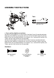
2. Front Handlebar Post, Tension Control Knob, and Foot Pedals Installation
Remove one M8x15 Bolt (23), one Ø8.4xØ25x2 Big Curve Washer (25), four Ø8 Flat
Washers (24), and four M8x10 Bolts (76) from the tube of the Front Main Frame (5).
Remove bolts with the S6 Allen Wrench provided.
Slide the Front Handlebar Post Cover (73) up to the Front Handlebar Post (6).
Insert the Tension Cable (40) through into the bottom hole of Front Handlebar Post (6) and
pull it out from the square hole of Front Handlebar Post (6).
Connect the Sensor Wire (61) and Extension Hand Pulse Sensor Wires I (65) from the Front
Main Frame (5) to the Extension Sensor Wire (64) and Extension Hand Pulse Sensor Wires
II (63) from the Front Handlebar Post (6).
Insert the Front Handlebar Post (6) onto the tube of the Front Main Frame (5) and secure
with one M8x15 Bolt (23), one Ø8.4xØ25x2 Big Curve Washer (25), four Ø8 Flat Washers
(24), and four M8x10 Bolts (76) that were removed. Tighten bolts with the S6 Allen Wrench
provided.
Slide the Front Handlebar Post Cover (73) down to the Front Main Frame (5).
Remove the M5x20 Bolt (36) and Ø5 Flat Washer (38) from the Tension Control Knob (14).
Remove bolt with the Multi Hex Tool with Phillips Screwdriver provided.
Put the cable end of resistance cable of Tension Control Knob (14) into the spring hook of
Tension Cable (40), see Figure A. Pull the resistance cable of Tension Control Knob (14)
up and force it into the gap of metal bracket of Tension Cable (40), see Figure B. Attach
the Tension Control Knob (14) onto the Front Handlebar Post (6) with the M5x20 Bolt (36)
and Ø5 Flat Washer (38) that were removed. Tighten bolt with the Multi Hex Tool with
Phillips Screwdriver provided.
Foot Pedals Installation
The Cranks, Foot Pedals, Pedal Shafts and Pedal Straps are marked “R” for Right and
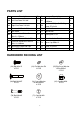
Allen Wrench S6
Tool:
Multi Hex Tool with Phillips Screwdriver
S10, S13, S14, S15
14
40
14
40
BA
76
76
36
38
6
40
14
46
73
24
23
25
24
40
59
60
5
65
61
64
63