JUPITER, ELLIPTICAL TRAINER ITEM NO: 93720 OWNER’S MANUAL IMPORTANT: Read all instructions carefully before using this product. owner’s manual for future reference. Retain this The specifications of this product may vary from this photo, subject to change without notice.
TABLE OF CONTENTS WARRANTY ------------------------------------------------------------------------------- 2 IMPORTANT SAFETY INSTRUCTIONS ------------------------------------------- 3 PARTS LIST ------------------------------------------------------------------------------- 4 HARDWARE PACKING LIST --------------------------------------------------------- 6 TOOLS -------------------------------------------------------------------------------------- 7 OVERVIEW DRAWING ---------------------------------------
ONE YEAR LIMITED WARRANTY LifeGear Inc. warrants to the original purchaser that this product is free from defects in material and workmanship when used for the purpose intended, under the conditions that it has been installed and operated in accordance with LifeGear's Owner's Manual. LifeGear's obligation under this warranty is limited to replacing or repairing free of charge, any parts which may prove to be defective under normal home use.
IMPORTANT SAFETY INSTRUCTIONS Basic precautions should always be followed, including the following important safety instructions when using this equipment: Read all instructions before using this equipment. 1. 2. 3. 4. 5. 6. 7. 8. 9. 10. 11. 12. 13. Read all instructions and follow it carefully before using this equipment. Make sure the equipment is properly assembled and tightened before use. Before exercise, in order to avoid injuring the muscle, warm-up exercise is necessary.
PARTS LIST No. Description Qty No. Description Qty 001 Main Frame Ø50x2 1 025 Washer Ø16xØ8x1.5 2 002L Left Foot Bar 40x25x1.5 1 026 Bolt M8x48 2 002R Right Foot Bar 40x25x1.5 1 027 Nylon Nut M6 10 003L Left Handrail Arm Ø32x1.5 1 028 Washer Ø6 11 003R Right Handrail Arm Ø32x1.5 1 029 Hexagon Head Bolt M6x40 6 004L Left Handrail Ø32x1.5 1 030 Tension Cable L=1600 1 004R Right Handrail Ø32x1.5 1 031 Washer Ø10.2xØ14xδ1.0 2 005 Front Post Ø50x1.
PARTS LIST No. Description Qty No. Description Qty 053 Bolt Cap S32 2 070 Left Cover 1 054 Foot Bar End Cap 2 071 Right Cover 1 055 Tension Control Knob 1 072 Bearing Cup Ø51.5 2 056 Computer (KB5128-2) 1 073 Bearing 2 057 Bolt M5x12 4 074 Bearing Nut I 15/16” 1 058 Hand Pulse Sensor with Wire L=580 2 075 Bearing Nut II 7/8” 1 059 Handrail Foam Grip Ø31xØ37x480 2 076 Washer Ø34.5xØ23x2.5 1 060 Spring Washer Ø8 8 077 Hexagon Nut 7/8” 1 061 Handrail End Cap Ø32x1.
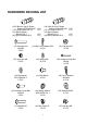
HARDWARE PACKING LIST (16R) Bolt for right U Shape Bracket Ø16x88.5xL23 (17R) Right Nylon Nut 1/2” (18) Wave Washer Ø28xØ17x0.3 (20) Spring Washer Ø12 (16L) Bolt for left U Shape Bracket Ø16x88.5xL23 (17L) Left Nylon Nut 1/2” (18) Wave Washer Ø28xØ17x0.
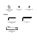
(51) Plastic Bushing Ø32xØ16x5xØ50 2 PCS (53) Bolt Cap S32 2 PCS (60) Spring Washer Ø8 8 PCS TOOLS Allen Wrench with Phillips Screwdriver 5mm 1 PC Allen Wrench 8mm 1 PC Multi Hex Tool S10, S13, S17, S19 1 PC 7
37 8 66 32 32 32 38 49 66 70 35 45 19 46 50 28 32 77 63 73 72 28 27 2L 38 57 6 58 16L 51 69 67 18 19 79 27 57 5 26 25 23 19 4R 15 14 48 34 19 50 28 46 68 85 20 17L 53 24 8 55 67 68 30 51 56 84 85 42 41 60 15 14 36L 65 64 29 48 19 34 3L 46 4L 41 60 42 47 76 75 54 39 27 40 33 10 12 43 44 59 61 69 62 15 14 19 35 3R 46 1 13 47 12 11 54 21 31 28 27 13 52 9 83 2R 43 49 7 28 44 45 33 59 61 17R 20 19 79 29 26 25 2
ASSEMBLY INSTRUCTIONS Tool: 15 14 15 10 38 12 38 Multi Hex Tool S10, S13, S17, S19 14 11 13 1 13 12 1. Front and Rear Stabilizers Installation Slide two Ø50 Front Stabilizer End Caps (38) onto each end of the Front Stabilizer (10). Position the Front Stabilizer (10) in front of Main Frame (1) and align bolt holes. Attach the Front Stabilizer (10) onto the front curve of the Main Frame (1) with two M10x60 Carriage Bolts (12), two Ø10 Big Curve Washers (14), and two M10 Cap Nuts (15).
A 65 64 B 54 30 55 30 5 54 41 60 42 30 41 42 60 Tool: 67 68 30 Allen Wrench with Phillips Screwdriver 5mm 1 2. Front Post and Tension Control Knob Installation Insert the Tension Cable (30) through into the bottom hole of Front Post (5) and pull it out from the square hole of Front Post (5). Connect the Sensor Wire (68) from the Main Frame (1) to the Extension Sensor Wire (67) from the Front Post (5).
Tool: 43 49 33 44 51 45 3R 5 3L 29 Multi Hex Tool S10, S13, S17, S19 Allen Wrench 8mm 2L 53 78 24 28 36L(R) 27 16L(R) 18 17L(R) 20 23 3. Left/Right Handrail Arms, Left/Right Foot Bars, and Left/Right Foot Pedals Installation Install the Ø32xØ16x5xØ50 Plastic Bushing (51) onto the left horizontal axis of the Front Post (5). Then attach the Left Handrail Arm (3L) onto the left horizontal axis of the Front Post (5) with one M10x25 Hexagon Head Bolt (43), one Ø14.5xØ10.3x2.
Hardware: (51) Plastic Bushing Ø32xØ16x5xØ50 2 PCS (43) Hexagon Head Bolt M10x25 2 PCS (44) Spring Washer Ø14.5xØ10.3x2.1 2 PCS (33) Big Washer Ø12.5xØ30x0.8 2 PCS (45) Washer Ø28x5 2 PCS (49) Bolt Cap S33 2 PCS (16R) Bolt for right U Shape Bracket Ø16x88.5xL23 (17R) Right Nylon Nut 1/2” (18) Wave Washer Ø28xØ17x0.3 (20) Spring Washer Ø12 (16L) Bolt for left U Shape Bracket Ø16x88.5xL23 (17L) Left Nylon Nut 1/2” (18) Wave Washer Ø28xØ17x0.
4R 4L 50 Tool: Multi Hex Tool S10, S13, S17, S19 28 3R 3L 47 5 4. Left and Right Handrails Installation Attach the Left/Right Handrails (4L, 4R) onto the Left/Right Handrail Arms (3L, 3R) with four M6x35 Bolts (47), four Ø6 Washers (28), and four M6 Cap Nuts (50). Tighten cap nuts with the Multi Hex Tool provided.
56 58 6 67 57 Tool: 41 60 42 58 5 Allen Wrench with Phillips Screwdriver 5mm 5. Handlebar and Computer Installation Remove four M5x12 Bolts (57) from the back of the Computer (56). Remove bolts with the 5mm Allen Wrench with Phillips Screwdriver provided. Insert the Hand Pulse Sensor Wires (58) from the Handlebar (6) into the hole on the Front Post (5) and then pull them out from the top end of the Front Post (5).
OPERATING THE COMPUTER SPECIFICATIONS: TMR (TIMER) ---------------------------- 0:00-99:59 MIN: SEC SPD (SPEED) --------------------------- 0.0-999.9 KM/H DIS (DISTANCE) ------------------------ 0.0-999.9 KM CAL (CALORIES) ----------------------- 0.0-999.
ADJUSTMENTS Adjusting the Tension Control Knob To increase the load, turn the tension control knob in a clockwise direction. To decrease the load, turn the tension control knob in a counterclockwise direction. Tension Control Knob Adjusting the Rear Stabilizer End Cap Turn the rear stabilizer end cap on the rear stabilizer as needed to level the elliptical trainer.
MAINTENANCE Cleaning The elliptical trainer can be cleaned with a soft cloth and mild detergent. Do not use abrasives or solvents on plastic parts. Please wipe your perspiration off the elliptical trainer after each use. Be careful not get excessive moisture on the computer display panel as this might cause an electrical hazard or electronics to fail. Please keep the elliptical trainer, specially, the computer console, out of direct sunlight to prevent screen damage.
WARM UP AND COOL DOWN ROUTINE The WARM-UP is an important part of any workout. The purpose of warming up is to prepare your body for exercise and to minimize injuries. Warm up for two to five minutes before aerobic exercising. It should begin every session to prepare your body for more strenuous exercise by heating up and stretching your muscles, increasing your circulation and pulse rate, and delivering more oxygen to your muscles.
QUADRICEPS STRETCH With one hand against a wall for balance, reach behind you and pull your right foot up. Bring your heel as close to your buttocks as possible. Hold for 15 counts and repeat with left foot. INNER THIGH STRETCH Sit with the soles of your feet together and your knees pointing outward. Pull your feet as close to your groin as possible. Gently push your knees toward the floor. Hold for 15 counts.