
Operation Manual


9
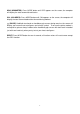
ASSEMBLY INSTRUCTIONS
1. Install the Front/Rear Stabilizers.
Attach the Front Stabilizer (7) onto the front curve
plate of the Main Frame (1) with two M10x57 Bolts
(9), Ø10 Big Curve Washers (11), and M10 Cap Nuts
(12).
Attach the Rear Stabilizer (8) onto the rear curve
plate of the Main Frame (1) with two M10x57 Bolts
(9), Ø10 Big Curve Washers (11), and M10 Cap Nuts
(12).
2. Install the Front Post and Tension Control
Knob.
Remove six M8x16 Bolts (38), Ø8 Spring Washers
(76), and Ø20xØ8 Curve Washers (39) from the tube
of the Main Frame (1).
Insert the Tension Cable (27) through into the bottom
hole of Front Post (5) and pull it out from the square
hole of Front Post (5). Connect the Sensor Wire II
(65) from the Main Frame (1) to the Sensor Wire I
(64) from the Front Post (5).
Insert the Front Post (5) onto the tube of the Main
Frame (1) and secure with six M8x16 Bolts (38), Ø8 Spring Washers (76), and Ø20xØ8
Curve Washers (39) that were removed.
Remove the Ø20xØ5 Curve Washer for Tension Control Knob (61) and M5x25 Bolt for
Tension Control Knob (62) from the Tension Control Knob (51). Put the cable end of
resistance cable of Tension Control Knob (51) into the spring hook of Tension Cable (27) as
shown in drawing A of figure 2. Pull the resistance cable of Tension Control Knob (51) up
and force it into the gap of metal bracket of Tension Cable (27) as shown in drawing B of
figure 2. Attach the Tension Control Knob (51) onto the Front Post (5) with the Ø20xØ5
Curve Washer for Tension Control Knob (61) and M5x25 Bolt for Tension Control Knob (62)
that were removed.
7
9
11
12
1
12
11
9
8
12
11
12
11
1
1
5
51
62
61
51
51
27
27
27
38
39
76
64
65
27
38
76
39
BA
8
7
6
2