
Operation Manual


7
ASSEMBLY INSTRUCTIONS
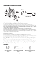
1. Front/Rear Stabilizers and Right/Left Foot Pedals Installation
Position the Front Stabilizer (6) in front of the Main Frame (1) and align bolt holes.
Attach the Front Stabilizer (6) onto the front curve of the Main Frame (1) with two M10 Cap
Nuts (34), two M10x60 Carriage Bolts (35), and two Ø10 Big Curve Washers (36). Tighten
cap nuts with the Multi Hex Tool provided.
Position the Rear Stabilizer (4) behind the Main Frame (1) and align bolt holes.
Attach the Rear Stabilizer (4) onto the rear curve of the Main Frame (1) with two M10 Cap
Nuts (34), two M10x60 Carriage Bolts (35), and two Ø10 Big Curve Washers (36). Tighten
cap nuts with the Multi Hex Tool provided.
Foot Pedals Installation
The Pedal Shafts and Pedals are marked “R” for Right and “L” for Left.
Insert the pedal shaft of Left Foot Pedal (20) into threaded hole in the left Crank (19). Turn
the pedal shaft by hand in the counter-clockwise direction until snug.
Note: DO NOT turn the pedal shaft in the clockwise direction, doing so will strip the
threads.
Tighten the pedal shaft of Left Foot Pedal (20) with the Multi Hex Tool provided.
Insert pedal shaft of Right Foot Pedal (21) into threaded hole in right Crank (19). Turn the
pedal shaft by hand in the clockwise direction until snug. Tighten pedal shaft of Right Foot
Pedal (21) with the Multi Hex Tool provided.
Hardware:
(34) Cap Nut M10
4 PCS
(35) Carriage Bolt M10x60
4 PCS
(36) Big Curve Washer Ø10
4 PCS
Tool:
Multi Hex Tool
36
34
21
20
4
6
35
34
36
35
1
19