
Install Instructions


THE LIFETIME LINING SYSTEM
™
Smooth wall and single wall chimney lining kit
Available in 3", 4", 5", 5½" and 6" in sections from 10' to 100'
The Lifetime Lining System is intended for use with heating appliances vented through a masonry chimney that burn home heating oil, natural or LP gas
and solid fuels (pellet, wood and coal). Use of experimental fuels voids the warranty. This lining system is not for use with Category ll, III, or IV gas burning
appliances as dened by the National Fuel Gas Code, NFPA 54, or other appliances that create positive pressures in the chimney system or that cause
condensation of corrosive acids on the liner of the chimney.
The Lifetime Lining System is intended for use in an unlined chimney with at least a nominal 4" of masonry all around, a properly built masonry chimney
with cracked clay tile liners, or to provide a properly sized ue for a heating appliance installed in a masonry chimney that otherwise meets existing codes.
The Lifetime Lining System may be used to reline a replace chimney. The liner must be connected to the top of the smoke chamber by a bottom plate or other
means that provides an air-tight and drip-free termination.
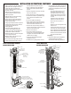
1 Stainless Steel Liner
1 Stainless Steel Tee
1 Stainless Steel Single Wall Liner
1 304 Series Stainless Steel Rain Cap
1 Stainless Steel Tee Cap
1 Stainless Steel Top Plate
If chimney requires eld drilling, use a 1/4"
stainless steel drill bit to drill through the
inner section of the chimney liner section.
Wall penetration assemblies are not to be
located directly behind a heating appliance.
The following criteria shall apply to a
connector to a masonry chimney:
It shall extend through the wall to the inner
face or liner but not beyond.
It shall be rmly cemented to masonry.
If a thimble is used to facilitate removal of
the chimney connector for cleaning, the
thimble shall be permanently cemented in
place with high-temperature cement.
The effective area of a connector for a
single appliance shall not be less than the
area of the appliance ue collar, unless it is
part of an engineered venting system.
Sizing:
Size the liner according to equipment
manufacturer’s instructions and/or local
building codes. The chimney liner must
be sized not less than that specied in the
appliance manufacturer’s instructions.
Local approval:
Contact local re or building ofcials about
restrictions and installation inspection in
your area.
Cleaning existing chimney:
The chimney must be clean and free
ofdebris.
All soot dirt and creosote including tar
and glaze creosote must be removed prior
toinstallation.
Proper cleaning of the chimney is a
warranty prerequisite.
The internal and external condition of the
chimney must be checked for safety and
repaired as necessary.
The chimney must terminate above the roof
line as per NFPA-211.
Run a guide cone up and down the
chimney to clear any obstructions and to
ascertain that the liner diameter will pass
through the chimney’s ue opening.
Choosing the correct type of
stainless steel:
Type 304/316 (or 304L/316L), 430 and
446 stainless can be used for wood, oil
and low efciency gas appliances. Type
304/316 can also be used as a replace
liner. The high efciency gas furnaces
require another type of venting system.
Refer to the manufacturer’s installation
instructions before connecting a liner to a
gas appliance.
Connection to UL listed direct
connect system:
The liner system may be connected
with a UL listed direct connect system
which is installed in accordance with the
manufacturer’s instructions. You must
use a stainless steel pipe connector or
stainless steel transition or slip connector
to make the connection. The liner must
also be sized (cross sectional area) the
same as the direct connect system.
Liner installation:
Inspect the chimney for cracked, loose
or missing bricks or stones. Check for
missing mortar joints. The chimney must
be a minimum of 4" thick throughout.
No chimney should be relined that is
not structurally sound. Also inspect
the air space clearances between the
exterior of the masonry chimney and
any combustibles. These clearances
must be in accordance with current
NFPA 211 standards or the local
building codes. Check the height of the
chimney to be certain it conforms to the
recognizedregulations.
This installation must include the rain cap,
a protective covering or housing for the
top of the chimney intended to prevent the
entry of rain, snow, animals and birds, and
to prevent down drafts.
Initial installation of chimneys, replaces
and vents shall allow inspection of the
surroundings to determine that the required
clearances have been maintained and that
correct provisions for support, stabilization,
future inspection and maintenance are
inplace.
Minimum air space clearance:
- Residential: 1" (25mm)
- Low-Heat: 2" (51mm)
- Medium-Heat: 4" (102mm)
All wood beams, joists, studs and
other combustible material shall have a
clearance to masonry replaces as follows:
- Not less than 2" (51mm) from the front
faces and sides.
- Not less than 4" (102mm) from the
back faces of masonry replaces
Remove a sufcient amount of brick and
mortar to allow access for the installation
of the tee’s snout at the base of the
chimney where the heating appliance
vent connector attaches to the tee of the
liningsystem.
Separate the tee from its snout.
Attach the tee to the liner with the
fasteners provided.
The Lifetime Lining System Includes:
PARTSLIST
INSTALLATIONINSTRUCTIONS
Continued on next page…