OUTDOOR STORAGE MODEL N° 60019 Co py OWNER’S MANUAL Keep this Identification Number in case you must contact our Customer Service Department.
IMPORTANT! PLEASE READ BEFORE BEGINNING ASSEMBLY Dear Valued Customer, We would like to congratulate you on your purchase of a Lifetime© Outdoor Storage Shed! We are confident that you have made the perfect choice and you will be very pleased with your new storage solution. Lifetime© Outdoor Storage is part of the family of products created and manufactured by Lifetime® Products, Inc.
IMPORTANT! PLEASE READ BEFORE BEGINNING ASSEMBLY s "EFORE BEGINNING ASSEMBLY REMOVE THE 0ARTS ,IST FROM THE CENTER OF THIS /WNER S -ANUAL AND TAKE AN inventory of the parts included with your Outdoor Storage Shed. Also, read through the entire instruction manual. It’s always a great practice to get a feel for the flow of the process and to familiarize yourself with the parts involved. But, try not to get ahead of yourself and start the process out of order. s &/,,/7 4(% ).3425#4)/.3 ).
REGISTER YOUR LIFETIME PRODUCT TODAY! There are benefits to registering your Lifetime product. With our new online product registration form, it’s fast and easy! Register with us at www.lifetime.com and enjoy these great benefits: s 2ECEIVE EXCLUSIVE MONEY SAVING OFFERS FROM "UY,IFETIME COM OUR ONLINE STORE AS WELL AS .
BEFORE BEGINNING ASSEMBLY Keep the hardware bags and their contents separate. If any parts are missing, call our Customer Service Department. 2EAD THE h#ONGRATULATIONSv LETTER ON PAGE Identify and inventory all parts and hardware using the parts and hardware lists and identifiers in this document. *Two adults required to complete assembly* (+ one adult suggested as an instruction reader) Only adults should set up the product. Do not allow children in the set-up area until assembly is complete.
ASSEMBLY GUIDES Refer to the following areas throughout the instructions to assist in the assembly process: This area is located at the top, left-hand corner of the page and indicates which tools and hardware are needed to complete the assembly steps on a page. TOOLS AND HARDWARE REQUIRED FOR THIS PAGE SEC This area is located at the top, right-hand corner of the page and shows an image of the product with shaded parts indicating which section is being assembled.
IMPORTANT NOTICES Level Surface Notice: Surface must be leveled before installation. We recommend building a level work space with a concrete or patio style surface. If the surface is not properly leveled, the Outdoor Shed will not assemble correctly. Proper surface leveling will save you time in the long run, so please do not ignore this step.
PARTS & HARDWARE LIST BOX 1 SHED PARTS BOX ID !': !'/ !'& !'( !') !'2 !&8 AFV !&9 !'1 !(" Description 2IGHT $OOR ,EFT $OOR %NTRY 'ABLE 2EAR 'ABLE 2EAR 'ABLE /UTER &LOOR 0ANEL #ENTER &LOOR 0ANEL 90” Shelf #ENTER 2OOF #AP 2OOF 0ANEL 2OOF 0ANEL FOR $OMED 3KYLIGHT Qty 1 ID Description Qty BHV GABLE ASSEMBLY HARDWARE (x2) !'0 ,OUVERED 6ENT !)1 6ENT 3CREEN !$7 X v 0AN (EAD 3CREW !%% X v &LAT 7ASHER !$:
PARTS IDENTIFIER BOX 1 SHED PARTS BOX Parts shown at 4% of actual size AGO (x1) Left Door AGZ (x1) Right Door AFV (x1) 90” Shelf (Rear View) AGF (x1) %NTRY 'ABLE AGH (x1) 2EAR 'ABLE (Rear View) AGI (x1) 2EAR 'ABLE (Rear View) AGR X Outer Floor Panel AFY X Center Roof Cap AGQ (x6) Roof Panel AFX X Center Floor Panel AHB X Roof Panel for Domed Skylight ! Note: Throughout the Parts & Hardware List, Part & Hardware Identifiers, and instructions are threeletter IDs.
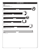
PARTS IDENTIFIER BOX 1 METAL PARTS KIT [CTD] Parts shown at 8% of actual size 75 1/2” AFC X Door End Channel 51” AFH (x6) 4RUSS 'UTTER #HANNEL 59 1/2” AFE (x1) Entry Header Bar 48” AFG X Roof Truss Brace 67 3/4” AFM X Wall/Shelf Support Channel 79 1/2” CRD X Door Hinge Tube 10
PARTS IDENTIFIER BOX 2 SHED PARTS BOX Parts shown at 4% of actual size 105 104 AGY (x1) Corner Wall Panel 104 106 AGN (x1) Corner Wall Panel 105 AGW (x1) Corner Wall Panel 106 107 AGL (x1) Corner Wall Panel 107 AHH (x1) Window Wall Panel AHD (x7) Wall Panel Parts shown at 4% of actual size SMALL PARTS KIT [BON] Parts shown at 8% of actual size SMALL PARTS BOX [BOO] Parts are not shown to scale 116 115 AIW (x1) Wood Block AFZ X Corner Shelf AHC (x4) Skylight AHE (x1) Window AGG (x1) Fron
PARTS & HARDWARE IDENTIFIER BOX 2 FLOOR ASSEMBLY HARDWARE [BQH] Hardware shown at actual size BQC X X v 0AN (EAD 3CREW /NLY USED ADC (x1) 0HILLIPS "IT AHO X Door Hinge Bushing TRUSS FRAME ASSEMBLY HARDWARE [BEA] x3 Parts shown to scale (*Unless otherwise noted) ADJ X 1/4” Cap Nut ADK (x6) #AP .
PARTS & HARDWARE IDENTIFIER BOX 2 GABLE ASSEMBLY HARDWARE [BHV] x2 Parts shown to scale (*Unless otherwise noted) ADZ (x4) 1/4” x 5/8” Pan-Head Screw (Only 4 used) *AIQ (x1) Vent Screen *AGP (x1) Louvered Vent AHS X v %ND 0LUG /NLY USED AEE (x5) X v Flat Washer ADV (x6) ADW (x5) 1/4” x 1 1/8” Pan-Head Screw X v 0AN (EAD 3CREW (Only 6 used) ACB (x1) X v 0AN (EAD 3CREW (Not used in this model) LEFT DOOR ASSEMBLY HARDWARE [BEF] Parts shown to scale (*Unless otherwise not
PARTS & HARDWARE IDENTIFIER BOX 2 DOOR & FRONT GABLE INSTALLATION HARDWARE [BHZ] Parts shown to scale (*Unless otherwise noted) ADZ (x6) 1/4” x 5/8” Pan-Head Screw *AIC (x1) ,EFT 'AP &LAP *AIM (x1) 2IGHT 'AP &LAP AHP X Cotter Pin ADX (x4) X v 0AN (EAD 3CREW DOMED SKYLIGHT ASSEMBLY HARDWARE [BEC] x2 Parts shown to scale (*Unless otherwise noted) ACR X X v #ARRIAGE "OLT AEE X X v &LAT 7ASHER ADK X #AP .
SEC TOOLS AND HARDWARE REQUIRED FOR THIS PAGE 1 Concrete (1 cu. yd.) SEC SITE PREPARATION - CONCRETE PLATFORM PREPARATION 1.1 The actual dimensions of your shed (at its widest and longest points) are 8’ x 10’. Ensure you select a site that will accommodate these measurements. The base of the shed is slightly smaller than this, so you will need to CREATE A LEVEL SURFACE THAT IS AT LEAST v X v 7E RECOMMEND USING A LEVEL CEMENT OR PATIO STYLE surface.
SEC TOOLS AND HARDWARE REQUIRED FOR THIS PAGE 1 2” x 4” x 90 1/2” (x9) (Not included) 2” x 4” x 118 1/4” X .OT INCLUDED 16d 3” Common Nail X .OT INCLUDED SEC ALTERNATIVE SITE PREPARATION: OPTION 1 - WOOD PLATFORM ASSEMBLY 1.2 %NSURE ALL LUMBER USED IS TREATED AND APPROVED FOR OUTDOOR USE "UILD OUTSIDE FRAME TO v X v outside dimensions: Note: Whenever possible, you should use the surfaces described on Page 7.
SEC TOOLS AND HARDWARE REQUIRED FOR THIS PAGE 1 22 1/4” x 93 1/2” x 3/4” Treated Plywood (x1) (Not included) 48” x 93 1/2” x 3/4” Treated Plywood X (Not included) SEC 1.3 8d 1 1/2” Common Nail X (Not included) ALTERNATIVE SITE PREPARATION: OPTION 1 - WOOD PLATFORM ASSEMBLY (CONT) Square up the frame by measuring from corner to corner. Measurement A should equal Measurement B. B A ! Note: All lumber must be rated for outdoor use. SEC 1.4 Cut Plywood into sizes called for on previous page.
SEC TOOLS AND HARDWARE REQUIRED FOR THIS PAGE 1 2” x 4” x 120” X .OT INCLUDED 2” x 6” x 89” X .OT INCLUDED Pea Gravel (9.8 Cubic Feet) L-Bracket (x4) (Not included) (Not included) 8d 1 1/2” Common Nail (x16) (Not included) ALTERNATIVE SITE PREPARATION: OPTION 2 - FILLED WOOD FRAME ASSEMBLY SEC 1.5 Cut outside frame to 8’ x 10’ outside dimensions. Lay boards flat so widest parts face up. Ensure frame is level. Square up the frame by measuring from corner to corner.
SEC 2 FLOOR ASSEMBLY HARDWARE REQUIRED HARDWARE BAG REQUIRED: BQH Hardware shown at actual size BQC X X v 0AN (EAD 3CREW /NLY USED ADC (x1) 0HILLIPS "IT AHO X Door Hinge Bushing LOCATED IN BOX 1 PLASTIC PARTS REQUIRED Parts shown at 4% of actual size AGR X Outer Floor Panel AFX X Center Floor Panel TOOLS REQUIRED Phillips Screwdriver Safety Glasses HARDWARE BAG REQUIRED: BQH ADC (x1) 0HILLIPS "IT 19
SEC TOOLS AND HARDWARE REQUIRED FOR THIS PAGE 2 NO HARDWARE REQUIRED FOR THIS STEP SEC FLOOR ASSEMBLY 2.1 Lay an Outer Floor Panel (AGR) flat on the ground. Hold a Center Floor Panel (AFX) at an angle as shown and fit tabs into slots. Lay Center Floor Panel flat. AFX AGR SEC 2.2 Hold the second Center Floor Panel (AFX) at an angle as shown and fit tabs into slots. Lay Center Floor Panel flat. AFX CAUTION Sharp objects may damage your floor.
SEC TOOLS AND HARDWARE REQUIRED FOR THIS PAGE AHO X SEC 2.3 Finally, connect the last Outer Floor Panel (AGR) to the second Center Floor Panel and lay flat. AGR SEC 2.4 $ECIDE WHICH END WILL BE THE FRONT OF YOUR SHED ,IFT THE &LOOR 0ANELS UP ENOUGH TO SLIDE THE TWO Door Hinge Bushings (AHO) under and up through the holes in the Floor Panels as shown.
SEC TOOLS AND HARDWARE REQUIRED FOR THIS PAGE 2 BQC X /NLY USED SEC 2.5 &ACE THE SEAM OF THE TWO ADJACENT &LOOR 0ANELS )NSERT TWO #8 x 1/2” Pan-Head Screws (BQC) near the seam of a Floor Panel and down into the tab of the adjacent Floor Panel at the locations shown. Repeat this step for both sides of each seam as shown. Insert Screws here. Seam Insert Screws here.
SEC TOOLS AND HARDWARE REQUIRED FOR THIS PAGE 2 IF YOU PLAN ON ANCHORING YOUR SHED, CHECK WITH YOUR LOCAL HARDWARE STORE FOR SUITABLE HARDWARE. SEC 2.6 ANCHORING THE SHED If you plan on anchoring your shed, you can anchor it to your platform through the four indentations near the corners of the floor. The anchoring hardware used depends on the platform.
SEC 3 TRUSS ASSEMBLY HARDWARE BAG REQUIRED: BEA (x3) HARDWARE REQUIRED Hardware shown at actual size (*Unless noted otherwise) ADY (x18) X v 3CREW ADJ (x6) 1/4” Cap Nut ADK (x18) #AP .
SEC TOOLS AND HARDWARE REQUIRED FOR THIS PAGE 3/8” ADY X ADK X SEC TRUSS ASSEMBLY 3.1 Stand a Truss Gutter Channel (AFH) upright and set a Truss Connector (AIP) inside the end of the Channel as shown. Align the holes and secure with one (1) #10 x 3/8” Pan-Head Screw (ADY) and one (1) #10 Cap Nut (ADK). AIP AIP ADY ADK AFH 3.
SEC TOOLS AND HARDWARE REQUIRED FOR THIS PAGE 3 3/8” ADY X ADK X SEC 3.2 Connect another Truss Gutter Channel (AFH) to the Truss Connector using one (1) #10 x 3/8” Pan-Head Screw (ADY) and one (1) #10 Cap Nut (ADK). Notch AFH ADY 3.
SEC TOOLS AND HARDWARE REQUIRED FOR THIS PAGE 3 3/8” ADY X ADK X SEC 3.3 Lay the Truss Assembly on its side, and align the holes in a Roof Truss Brace (AFG) with those circled on the Truss 'UTTER #HANNELS AS SHOWN AFG SEC 3.4 3ECURE THE 2OOF 4RUSS "RACE TO THE 4RUSS 'UTTER #HANNEL USING TWO #10 x 3/8” Pan-Head Screws (ADY) AND TWO #10 Cap Nuts (ADK). Repeat this step for the other end of the Roof Truss Brace. ADK ADY ADK WARNING ! Do not overtighten the Cap Nut.
SEC TOOLS AND HARDWARE REQUIRED FOR THIS PAGE 7/16” X ADJ (x6) 12 11/16” ADH X .OT TO SCALE SEC 3.5 With the Truss Assembly on its side, slide a 1/4” Threaded Rod (ADH) through the Roof Truss Brace and Truss Connector as shown. Secure the top and bottom of the 1/4” Threaded Rod with a 1/4” Cap Nut (ADJ). Tighten all hardware. The 1/4” Threaded Rod will still spin freely. Set aside. Repeat this section for the second and third Truss Assemblies.
SEC 4 WALL PANEL INSTALLATION HARDWARE BAG REQUIRED: BHY HARDWARE REQUIRED Hardware shown at actual size ADZ (x58) 1/4” x 5/8” Pan-Head Screw (Not all screws will be used) PLASTIC PARTS REQUIRED LOCATED IN BOX 2 Part shown at 4% of actual size 104 AGY (x1) Corner Wall Panel 104 105 AGN (x1) Corner Wall Panel 105 AHD (x7) Wall Panel 106 AGW (x1) Corner Wall Panel 106 AGL (x1) Corner Wall Panel 107 AHH (x1) Window Wall Panel TOOLS REQUIRED Phillips Screwdriver 107 SMALL PARTS BOX REQUIRED:
SEC TOOLS AND HARDWARE REQUIRED FOR THIS PAGE 4 ADZ X AIW (x1) Wood Block WALL PANEL INSTALLATION SEC Fold Corner Wall Panel 105 (AGN). Fit tabs of Panel into the front, left corner of your Floor (while facing shed). Place a Wood Block (AIW) under the floor panel, directly under the first tab, then pull down on the Corner Wall Panel until the tab snaps into place. Move the Wood Block under the next tab and repeat. 4.
SEC TOOLS AND HARDWARE REQUIRED FOR THIS PAGE ADZ X AIW (x1) Wood Block SEC 4.3 Fold Corner Wall Panel 107 (AGL). Snap into place and fasten at the top hole with the required hardware. AGL AIW SEC 4.4 Insert two Wall Panels (AHD) along the back side of shed. Ensure the tops are level and the holes line up before fastening the Panels through the top holes using the required hardware.
SEC TOOLS AND HARDWARE REQUIRED FOR THIS PAGE ADZ (x4) AIW (x1) Wood Block SEC 4.5 Fold Corner Wall Panel 106 (AGW) and fasten it to the rear Wall Panel through the top hole using the required hardware. AGW AIW SEC 4.6 Snap three Wall Panels (AHD) into place along the right side of the shed. The Window Wall Panel may be inserted in any side Wall Panel position. Ensure the tops of the Wall Panels are even and the holes align.
SEC TOOLS AND HARDWARE REQUIRED FOR THIS PAGE ADZ (x45) AIW (x1) Wood Block SEC 4.7 Fold Corner Wall Panel 104 (AGY) and snap it into place at the right, front corner of the Floor as shown. Fasten it to the Wall Panel through the top hole using the required hardware. Finish fastening all Panels together with the rest of the 1/4” x 5/8” Pan-Head Screws (ADZ) for all holes.
SEC 5 LEFT DOOR ASSEMBLY HARDWARE BAG REQUIRED: BEF HARDWARE REQUIRED Hardware shown at actual size ADW X X v 0AN (EAD 3CREW ABU X v X v #ARRIAGE "OLT 0ART SHOWN AT OF ACTUAL SIZE AHM X Deadbolt Latch ADJ X 1/4" Cap Nut AEE X X v &LAT 7ASHER Part shown at 15% of actual size AIB (x1) Left Door Strike Plate AHZ (x1) Left Door Handle AIA (x1) Left Door Lock Bracket METAL PARTS KIT REQUIRED: CTD METAL PARTS REQUIRED Part shown at 8% of actual size 75 1/
SEC TOOLS AND HARDWARE REQUIRED FOR THIS PAGE AHM X SEC LEFT DOOR ASSEMBLY 5.1 Rest the Left Shed Door (AGO) with front side down. Slide a Door Hinge Tube (CRD) through the hole in the Door as shown. CRD AGO Back of Door SEC 5.2 Position the Deadbolt Latches (AHM) in the slots at the top and bottom of the Door, then slide the Door End Channel (AFC) onto the Door as shown.
SEC TOOLS AND HARDWARE REQUIRED FOR THIS PAGE 5 7/16” ABU X AIB (x1) ADJ X AIA (x1) SEC 5.3 Slip the Left Door Strike Plate (AIB) over the Left Shed Door and align the holes. AIB ! Note: You may need to nudge the Door End Channel to make these holes line up with the gap in the Door. SEC 5.4 Attach the Left Door Lock Bracket (AIA) to the Left Door Strike Plate with two 1/4” x 1 1/2” Carriage Bolts (ABU) and two 1/4” Cap Nuts (ADJ). ADJ WARNING AIA Do not overtighten the Cap Nut.
SEC TOOLS AND HARDWARE REQUIRED FOR THIS PAGE 5 ADW X AEE X SEC 5.5 Attach the Left Door Handle (AHZ) USING THREE #10 x 1/2” Flat Washers (AEE) AND THREE #10 x 3/4” Pan-Head Screws (ADW).
SEC 6 RIGHT DOOR ASSEMBLY HARDWARE BAG REQUIRED: BEG HARDWARE REQUIRED Hardware shown at actual size AEE (x5) X &LAT 7ASHER /NLY ARE USED ABV X X #ARRIAGE "OLT AHY (x1) Latch Spring AIL (x1) Right Door Lock Bracket AHV (x1) Door Latch AIO (x1) Thumb Lever AAB X 1/4” Centerlock Nut AEB X 1/4” Flat Washer ADW (x4) X 0AN (EAD 3CREW 0ART SHOWN AT OF ACTUAL SIZE AHX (x1) Latch Cover Plate ADB X v X v 3TEEL 3PACER Part shown at 15% of actual size
SEC TOOLS AND HARDWARE REQUIRED FOR THIS PAGE NO HARDWARE REQUIRED FOR THIS PAGE SEC 6.1 RIGHT DOOR ASSEMBLY Rest the Right Shed Door (AGZ) with front side down. Slide a Door Hinge Tube (CRD) through the hole in the Door as shown. CRD Back of Door AGZ SEC 6.2 Slide the Door End Channel (AFC) onto the Door as shown.
SEC TOOLS AND HARDWARE REQUIRED FOR THIS PAGE NO HARDWARE REQUIRED FOR THIS PAGE SEC 6.3 Fit knobs of Thumb Lever (AIO) into the grooves of Right Door Handle (AIK). Groove Knob AIO AIK SEC 6.4 Rotate the Thumb Lever into the Right Door Handle. Slide forward until the knobs fit into the holes in the Handle.
SEC TOOLS AND HARDWARE REQUIRED FOR THIS PAGE 7/16” ABV X 6 ADW X AEB X ADB X AEE X AAB X SEC 6.5 !TTACH THE 2IGHT (ANDLE !SSEMBLY TO THE $OOR USING THREE #10 x 1/2” Flat Washers (AEE) AND THREE #10 x 3/4” Pan-Head Screws (ADW). AIO AIK ADW AEE ADW AEE CAUTION Do not overtighten. Overtightening may damage parts and void warranty. SEC 6.6 Install Handle Latch assembly onto the Right Shed Door using the required hardware.
SEC TOOLS AND HARDWARE REQUIRED FOR THIS PAGE 6 AHY (x1) AHW (x1) ADW (x1) SEC 6.7 Line up the hole in the Latch Block (AHW) with the hole in the Thumb Lever and secure with one (1) #10 X 3/4” PanHead Screw (ADW). 8.7 ADW AHW Lip ! Note: The lip of the Latch Block (AHW) fits under the Thumb Lever (AIO). SEC 6.8 Attach Latch Spring (AHY) to the Door Latch (AHV) and the Latch Cover Plate (AHX). Set the Door aside.
SEC 7 GABLE ASSEMBLY HARDWARE REQUIRED HARDWARE BAG REQUIRED: BHV (x2) Hardware shown at actual size AEE (x10) X v &LAT 7ASHER ADW (x10) X v 0AN (EAD 3CREW ADZ (x8) 1/4” x 5/8” Pan-Head Screw (Only 4 used) AHS (x4) End Plug /NLY USED ADV X 1/4” x 1 1/8” Pan-Head Screw (Only 6 used) ACB X X v 0AN (EAD 3CREW (Not used in this model) Parts shown at 8% of actual size AGP X Louvered Vent AIQ X Vent Screen METAL PARTS REQUIRED METAL PARTS KIT REQUIRED: CTD
SEC TOOLS AND HARDWARE REQUIRED FOR THIS PAGE ADZ (x4) SEC REAR GABLE ASSEMBLY 7.1 Lay the edge of Rear Gable 2 (AGI) over Rear Gable 1 (AGH) as shown, and align the four holes. AGI AGH SEC 7.2 #ONNECT 2EAR 'ABLES together using four (4) 1/4” x 5/8” Pan-Head Screws (ADZ) as shown. ADZ ADZ ! Note: Only use a hand screwdriver in this step.
SEC TOOLS AND HARDWARE REQUIRED FOR THIS PAGE 7 AEE (x5) ADW (x5) SEC 7.3 ,AY 2EAR 'ABLE !SSEMBLY m AT ON THE GROUND OVER THE Vent Screen (AIQ) and Louvered Vent (AGP). Align the holes in THE ,OUVERED 6ENT WITH THOSE IN THE 2EAR 'ABLE !SSEMBLY AIQ AGP SEC 7.4 !FTER ALIGNING THE HOLES PRESS DOWN l RMLY ON THE 2EAR 'ABLE !SSEMBLY WHILE INSERTING THE l VE #10 x 3/4” PanHead Screws (ADW) and the five (5) #10 x 1/2” Flat Washers (AEE).
SEC TOOLS AND HARDWARE REQUIRED FOR THIS PAGE ADW (x5) 7 AEE (x5) SEC ENTRY GABLE ASSEMBLY 7.5 Lay Entry Gable (AGF) flat on the ground over the Vent Screen (AIQ) and Louvered Vent (AGP) as shown. Align the holes IN THE ,OUVERED 6ENT WITH THOSE IN THE %NTRY 'ABLE AGF AIQ AGP SEC 7.6 !FTER ALIGNING THE HOLES PRESS DOWN l RMLY ON THE %NTRY 'ABLE WHEN INSERTING THE l VE #10 x 3/4” Pan-Head Screws (ADW) and the five (5) #10 x 1/2” Flat Washers (AEE).
SEC TOOLS AND HARDWARE REQUIRED FOR THIS PAGE 7 ADV (x6) AHS X SEC 7.7 Insert an End Plug (AHS) into each end of Entry Header Bar (AFE). AHS AFE The flat screw holes should face away from the Entry Gable. AHS The indented, rectangular hole faces downward, and is closer to the right side of the Entry Gable. ! Note: Only use a hand screwdriver in this step. SEC 7.8 !TTACH THE %NTRY (EADER "AR TO THE %NTRY 'ABLE !SSEMBLY AND SECURE WITH SIX 1/4” x 1 1/8” Pan-Head Screws (ADV). Set aside.
SEC 8 DOMED SKYLIGHT ASSEMBLY HARDWARE REQUIRED HARDWARE BAG REQUIRED: BEC (x2) Hardware is actual size (*Unless indicated otherwise) ACR X X v #ARRIAGE "OLT AEE X X v &LAT 7ASHER ADK X #AP .
SEC TOOLS AND HARDWARE REQUIRED FOR THIS PAGE 8 AHI X (Not to scale) SEC 8.1 DOMED SKYLIGHT ASSEMBLY Use a plain screwdriver to gently remove any excess plastic from the twelve holes in the Roof Panel for Domed Skylight (AHB). It’s important that the hole stay square; try not to round the corners of the edges of the holes. AHB ! Note: Use a plain screwdriver to remove any excess plastic from all holes in Panel. Ensure the holes remain square. SEC 8.
SEC TOOLS AND HARDWARE REQUIRED FOR THIS PAGE NO HARDWARE REQUIRED FOR THIS PAGE SEC 8.3 Insert a screwdriver through the Butyl Tape and into the twelve holes. This will help you align the holes in the Domed Skylight with those in the Roof Panel for Domed Skylight in the next step. Exterior View 9.4 SEC 8.4 Remove the protective plastic film from both sides of the Domed Skylight (AGB). Carefully align the holes in the Domed Skylight with those in the Butyl Tape.
SEC TOOLS AND HARDWARE REQUIRED FOR THIS PAGE 8 3/8” ADK X AEE X ACR X SEC 8.5 Insert one #10 x 5/8” Carriage Bolt (ACR) through each hole in the Domed Skylight. Press the Bolt through the Butyl Tape and through the Roof Panel for Domed Skylight. The necks of the Carriage Bolts fit into the square holes in the Domed Skylight. Top Neck of Carriage Bolt Exterior View SEC 8.
SEC 9 DOOR & ENTRY GABLE INSTALLATION HARDWARE BAG REQUIRED: BHZ HARDWARE REQUIRED Hardware shown at actual size (*Unless noted otherwise) AHP X Cotter Pin ADZ (x6) 1/4” x 5/8” Pan-Head Screw *AIM (x1) 2IGHT 'AP &LAP ADX (x4) X v 0AN (EAD 3CREW FROM SECTIONS 5, 6, & 7 PLASTIC PARTS REQUIRED Parts shown at 4% of actual size Rear View Entry Gable Assembly Left Door Assembly Right Door Assembly TOOLS REQUIRED Phillips Screwdriver Pliers *AIC (x1) ,EFT 'AP &LAP Safety Glasses 52
SEC TOOLS AND HARDWARE REQUIRED FOR THIS PAGE 9 AHP X SEC 9.1 DOOR INSTALLATION Align the hole in the bottom of the Hinge of the Left Door Assembly with the hole in the Door Hinge Bushing on the Floor of your shed, and insert the Door Hinge Tube into the Door Hinge Bushing. Left Door Assembly SEC 9.2 Insert a Cotter Pin (AHP) through the Bushing and Door Hinge. Use a pair of pliers to bend the ends of the Cotter Pins outward. Repeat these steps for the Right Door Assembly.
SEC TOOLS AND HARDWARE REQUIRED FOR THIS PAGE ADZ (x6) SEC 9.3 2 ADULTS REQUIRED FOR THE STEPS ON THIS PAGE ENTRY GABLE INSTALLATION Slide the two holes in the Entry Gable Assembly down over the Door Hinge Tubes as shown. SEC 9.4 !LIGN THE HOLES IN THE SIDES OF THE %NTRY 'ABLE !SSEMBLY WITH THOSE IN THE TOPS OF THE #ORNER 7ALL 0ANELS AND secure with six (6) 1/4” x 5/8” Pan Head Screws (ADZ) at the locations indicated.
SEC TOOLS AND HARDWARE REQUIRED FOR THIS PAGE 9 ADX (x4) AIC (x1) (Not to scale) AIM (x1) (Not to scale) SEC GAP FLAP INSTALLATION 9.5 Attach the Right Left Gap Flaps (AIM AIC) to the top, right and left corners of the Doors as shown.
SEC 10 TRUSS, REAR GABLE, & ROOF INSTALLATION HARDWARE REQUIRED HARDWARE BAG REQUIRED: BHX Hardware shown at actual size (*Unless otherwise noted) ADZ X 1/4” x 5/8” Pan-Head Screw (Not all screws will be used) ADX X X v 0AN (EAD 3CREW AED X X v &ENDER 7ASHER METAL PARTS REQUIRED AXX X Truss Hole Insert SMALL PARTS KIT REQUIRED: BON Parts shown at 8% of actual size AFL (x10) Roof Support Strip ! Note: The hole in the Roof Support Strip is for manufacturing purposes on
SEC TOOLS AND HARDWARE REQUIRED FOR THIS PAGE 10 NO HARDWARE REQUIRED FOR THIS STEP 3 ADULTS REQUIRED FOR STEPS 10.1 - 10.8 SEC TRUSS & ROOF INSTALLATION 10.1 Place the ends of a Truss Assembly into the notches on the Wall Panels as shown. While one adult holds the Truss Assembly in place, set a Roof Panel for Domed Skylight Assembly ONTO THE 4RUSS !SSEMBLY AND &RONT 'ABLE The edge of the Roof Panel fits down inside the Truss Channel.
SEC TOOLS AND HARDWARE REQUIRED FOR THIS PAGE (Not actual size) 10 AFL X ADZ X SEC 10.3 7ITH THE 2OOF 0ANEL FOR $OMED 3KYLIGHT IN POSITION BETWEEN THE 'ABLE AND 4RUSS SLIDE TWO Roof Supports (AFL) into place within the notches of the Roof Panel for Domed Skylight. The bottom lip of the Roof Panel fits over the Wall Panel. The top of the Wall Panel fits into the groove near the bottom of the Roof Panel.
SEC TOOLS AND HARDWARE REQUIRED FOR THIS PAGE 10 (Not actual size) AFL X ADZ X SEC 10.5 Place the ends of a second Truss Assembly into the notches on the next Wall Panel and Window Wall Panel as shown. SEC 10.6 While one adult holds the Truss Assembly in place, attach two more Roof Panels (AGQ) and Roof Support Strips (AFL) into the Truss Assemblies as shown. The edge of the Roof Panels fit down inside the Truss Channels.
SEC TOOLS AND HARDWARE REQUIRED FOR THIS PAGE 10 (Not actual size) AFL X ADZ X SEC 10.3 Place the ends of the last Truss Assembly into the notches on the next set of Wall Panels as shown. SEC 10.4 While one adult holds the Truss Assembly in place, attach two more Roof Panels (AGQ) and Roof Support Strips (AFL) into the Truss Assembly as shown. The edge of the Roof Panels fit down inside the Truss Channels. Ensure the alignment nubs in the Roof Panels fit into the notches on the Trusses.
SEC TOOLS AND HARDWARE REQUIRED FOR THIS PAGE 10 (Not actual size) AFL X ADZ X SEC 10.7 !TTACH THE 2EAR 'ABLE !SSEMBLY TO THE SHED AS SHOWN AND SECURE WITH FOURTEEN 1/4” x 5/8” Pan-Head Screws (ADZ). Rear Gable Assembly SEC 10.8 Secure the last Roof Panel for Domed Skylight (AHB) and Roof Panel (AGQ) ONTO THE 4RUSS !SSEMBLY AND 2EAR 'ABLE Assembly using the required hardware. The edge of the Roof Panels fit down inside the Truss Channels.
SEC TOOLS AND HARDWARE REQUIRED FOR THIS PAGE 10 ADZ X 2 ADULTS REQUIRED FOR STEP 10.9 - 10.10 SEC 11.9 SEC ROOF CAP INSTALLATION 10.9 Starting at the front side of your shed, attach the Front Roof Cap (AGG) TO THE 2OOF 0ANELS AND %NTRY 'ABLE Continue moving to the rear attaching the Center Roof Caps (AFY). Finally, attach the Rear Roof Cap (AFW) to the Roof 0ANELS AND 2EAR 'ABLE AFW ! Note: Use only a hand screwdriver for this step. AFY AFY AFY AGG SEC SEC 11.10 11.
SEC TOOLS AND HARDWARE REQUIRED FOR THIS PAGE 10 ADX X AXX X (Not to scale) AED X SKYLIGHT INSTALLATION SEC SEC 10.11 11.12 Pre-fold Skylight (AHC) before installing. Push folded Skylight up through opening between Roof Caps; open Skylight; use tabs to pull Skylight down into place. Fasten Skylight in place with six (6) #10 x 1” Fender Washers (AED) and six (6) #10 x 1/2” Pan-Head Screws (ADX) (pull down on tabs while inserting screws to provide resistance).
SEC 11 SHELF INSTALLATION HARDWARE BAGS REQUIRED: BHH, BHI (x2) HARDWARE REQUIRED Hardware shown at actual size Parts shown at 15% of actual size ADZ (x14) 1/4” x 5/8” Pan-Head Screw AIY X Shelf Support Bracket Hardware shown at actual size ADZ (x8) 1/4” x 5/8” Pan-Head Screw METAL PARTS KIT REQUIRED: CTD METAL PARTS REQUIRED Parts shown at 8% of actual size 67 3/4” AFM X Wall/Shelf Support Channel PLASTIC PARTS REQUIRED LOCATED IN BOX 1 & SMALL PARTS KIT: BON Part shown at 4% of actual
SEC TOOLS AND HARDWARE REQUIRED FOR THIS PAGE 11 ADZ (x8) SEC WALL/SHELF SUPPORT CHANNEL INSTALLATION 11.1 Insert a Shelf Support Channel (AFM) into the slots in the Wall Panels directly below the Right Truss notch, and secure with four (4) 1/4” x 5/8” Pan-Head Screws (ADZ). Insert a second Shelf Support Channel in the slot directly to the right of the Left Truss Notch and secure with four (4) 1/4” x 5/8” Pan-Head Screws. Insert Channels here.
SEC TOOLS AND HARDWARE REQUIRED FOR THIS PAGE 11 ADZ (x6) SEC 90” SHELF INSTALLATION 11.2 Set a Shelf Support Bracket (AIY) into the slots of each of the Shelf Support Channels. The slots must be at the same height. AIY AIY ! Note: Insert Shelf Support Bracket at an angle. SEC 11.3 Fold up flaps on the end of 90” Shelf (AFV). Set Shelf on Brackets with indentations toward wall, and secure with six (6) 1/4” x 5/8” Phillips Pan-Head Screws (ADZ).
SEC TOOLS AND HARDWARE REQUIRED FOR THIS PAGE 11 ADZ (x8) SEC 11.4 CORNER SHELF INSTALLATION Fold up edges of a Corner Shelf (AFZ). Line-up holes in the Corner Shelf with a set of pre-made holes in any Corner Panel as shown. Secure with four (4) 1/4” x 5/8” Phillips Pan-Head Screws (ADZ). Repeat this step for the second Corner Shelf. Holes Holes AFZ WARNING The total weight placed on a Corner Shelf cannot exceed 10 lb. (4.5 kg).
SEC 12 WINDOW INSTALLATION HARDWARE REQUIRED HARDWARE BAG REQUIRED: BEJ Hardware shown at actual size (*Unless indicated otherwise) ADZ (x4) 1/4” x 5/8” Pan-Head Screw *AIS X Window Latch ADY (x1) X v 0AN (EAD 3CREW PLASTIC PARTS REQUIRED SMALL PARTS KIT REQUIRED: BON Part shown at 4% of actual size AHE (x1) Window TOOLS REQUIRED Phillips Screwdriver Safety Glasses 68
SEC TOOLS AND HARDWARE REQUIRED FOR THIS PAGE ADZ (x4) 12 AIS X (Not to scale) ADY (x1) SEC WINDOW INSTALLATION 12.1 Remove the plastic protective film from both sides of the Window (AHE) and slide the Window into the grooves along the sides of the opening in the Window Wall Panel (Fig. 1). Insert the #10 x 3/8” Pan-Head Screw (ADY) into the hole AT THE BOTTOM OF THE 7INDOW &IG UNTIL m USH !TTACH A Window Latch (AIS) above each corner of the Window as shown.
SEC 13 DOOR ALIGNMENT HARDWARE REQUIRED NO HARDWARE PROVIDED FOR THIS SECTION TOOLS REQUIRED Phillips Screwdriver Rubber Mallet SMALL PARTS BOX REQUIRED: BOO AIX (x4) Wood Shim (Provided) Level 70 Safety Glasses
SEC TOOLS AND HARDWARE REQUIRED FOR THIS PAGE 13 AIX (x4) SEC DOOR ALIGNMENT 13.1 In some cases, the shed doors may not completely line up at the tops (fig. 1).
CLEANING & CARE 12 Congratulations on your Lifetime® product purchase. By following the instructions below, your new Lifetime product should provide you with years of service and enjoyment. Cleaning and Care The polyethylene panels are stain- and solvent-resistant. Most stains can be removed, using a mild soap and a soft-bristled brush. Abrasive cleaning materials may scratch the plastic and are not recommended.
LIFETIME OUTDOOR SHED EQUIPMENT 10-YEAR LIMITED FACTORY WARRANTY THE MANUFACTURER RESERVES THE RIGHT TO MAKE SUBSTITUTIONS TO WARRANTY CLAIMS IF PARTS ARE UNAVAILABLE OR OBSOLETE. 1. Lifetime outdoor sheds are warranted to the original purchaser to be free from defects in material or workmanship FOR A PERIOD OF TEN YEARS FROM THE DATE OF ORIGINAL RETAIL PURCHASE 4HE WORD hDEFECTSv IS DEl NED AS IMPERFECTIONS THAT impair the use of the product.
ENHANCE YOUR LIFETIME® PURCHASE BY ADDING ACCESSORIES OR OTHER GREAT PRODUCTS: To purchase accessories or other Lifetime Products, visit us at: www.lifetime.