- Installation and Maintenance Instructions Model SL580 Heavy Duty Slide Gate Operator Model SL590 Heavy Duty, Harsh Environment Slide Gate Operator Doc 01-G0547 Rev D
Contents Contents General Information________________________________________________________ 4 Supplied Parts _______________________________________________________________________ 4 Model Classifications _________________________________________________________________ 4 Specifications _______________________________________________________________________ 5 Operator Dimensions__________________________________________________________________ 6 Cycle Rates ____________________________________________
Contents 3 Troubleshooting___________________________________________________________27 1. Power___________________________________________________________________________ 27 2. Accessories ______________________________________________________________________ 28 3. Primary Voltage Circuit ____________________________________________________________ 28 4.
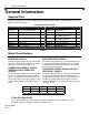
General Information General Information Supplied Parts Inspect the operator for possible shipping damage and shortage of parts. Some ordered accessories may be packed separately. For Models SL580 & SL590 PART # DESCRIPTION QTY. PART # 01-G0547 SL580 & SL590 MANUAL 1 82-QN43-12 01-G0582 GATE SAFETY INSTR.
General Information 5 Specifications Model H.P. Gate Speed Max. Gate Weight SL580 SL580 SL580 SL580 ½ ¾ 1 1-1/2 ½ ¾ 1 1-1/2 2 11”/sec. 11”/sec. 11”/sec. 11”/sec. 12”/sec. 12”/sec. 12”/sec. 12”/sec. 12”/sec. 1000 lbs. 1300 lbs. 1600 lbs. 1900 lbs. 1100 lbs. 1400 lbs. 1700 lbs. 2100 lbs. 2500 lbs. SL590 SL590 SL590 SL590 SL590 Max. Cant’l. Width 25 ft. 30 ft. 35 ft. 40 ft. 25 ft. 30 ft. 35 ft. 40 ft. 45 ft. Max. O/H Width 45 ft. 60 ft. 70 ft. 80 ft. 45 ft. 60 ft. 70 ft. 80 ft. 90 ft. Max.
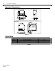
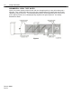
General Information Operator Dimensions MODEL SL580 25-7/8” 13” 34-3/4” 21-1/8” 10-7/8” NOTE: Diagonal support braces shown are standard only on 1-1/2hp operators. MODEL SL590 16-1/2” 24” 13-1/2” 30” 12” MIN. 22-1/2” ALLOW FOR DOOR OPENING 3” DIA. PIPE (Not Supplied with Operator) 01-G0547F5 Figure 1 Cycle Rates MODEL APPLICATIONS SL580 Heavy Duty, Industrial SL590 Heavy Duty, Industrial with Harsh Environment â Cycle = One full open and one full close.
Safety Information Safety Information Vehicular gate systems provide convenience and security. Gate systems are comprised of many component parts. The gate operator is only one component. Each gate system is specifically designed for an individual application. Gate operating system designers, installers and users must take into account the possible hazards associated with each individual application.
Safety Information STEP 2: DURING INSTALLATION 1 Disconnect power at service panel before making any electrical connection. 2 Avoid pinch points, be aware of all moving parts. 3 Adjust clutch or load sensing device to minimum force setting. 4 Do not over-tighten cutch or adjust force setting above minimum. 5 Install controls where user cannot touch gate while operating controls. 6 Install controls where user has full view of gate operation.
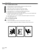
Safety Information 9 Safety Precautions for Open-Roller Gates and Ornamental “Grill OPEN-ROLLER GATES Injuries occur when people get their or feet caught between the top or bottom of the gate and the gate roller. This potential pinch-point should be guarded against at all times. Enclosed style gate tracks are available for refitting of these rollers from many fence suppliers. Also, roller guards are available for installing over the rollers.
Safety Information ORNAMENTAL “GRILL TYPE” GATES Injuries occur when people put their hands and arms through openings in the grill and the gate is operated. They cannot retract their arm and it gets caught between the moving gate grill and the stationary fence post or fence. This potential hazard can be averted by placing a 4’ screen mesh on the gate to prevent access through openings anywhere the gate may travel. See Safety Brochure for details.
Pre-Installation Check-List Pre-Installation Check-List Φ Check the gate. It must operate smoothly and freely. If necessary, lubricate, adjust, or repair the gate prior to operate installation. The gate must be level and plumb. Φ Some gates may only be as wide as the gate opening. They may require a back frame to be constructed to allow for chain attachments. Φ Double check the size and weight of the gate to make sure that this operator is proper for this application.
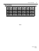
Safety Information Single Phase WIRE GAUGE 3 Phase HP 115 VAC 230 VAC 230 VAC 460 VAC 575 VAC 1/3 1/2 3/4 1 1-1/2 2 1/3 1/2 3/4 1 1-1/2 2 684 473 324 237 158 -432 299 204 149 100 -- 3,077 2,051 1,231 947 648 437 1,942 1,295 777 597 409 299 4,737 2,842 2,030 1,421 947 711 2,990 1,794 1,281 897 589 448 14,211 14,211 7,105 5,684 4,060 2,842 8,969 8,969 4,484 3,587 2,562 1,794 35,527 17,764 11,842 8,882 5,921 4,441 22,422 11,211 7,474 5,605 3,737 2,803 10 1/3 1/2 3/4 1 1-1/2 2 271 187 128 9
Features Features Operator Features SOLENOID ACTIVATED, CALIPER DISC BRAKE SOLENOID BRAKE The brake (Figure 5) minimizes overtravel caused by gate coasting. An added feature of the brake is to assist in preventing backdriving of the gate. The brake is spring applied whenever the motor is not running. Anytime the motor is running, the electric solenoid physically releases the brake. Important: periodically check and adjust the brake mechanism. See page 31.
Features MANUAL OPERATION The gate cannot be moved manually when the operator drive mechanism is connected to it. To disconnect the gate from the drive system, follow the directions below and refer to Figure 7. DISCONNECT SL580 SL590 01-G0547F8 Figure 7 MODEL SL580 – Slide out the lock bar located underneath the cover and remove the cover. Pull the disconnect chain and engage it in the slot provided. The gate may now be moved manually. To re-engage the operator, release the chain from the slot.
Features 15 System Features ACTIVITY LED Steady indication when gate is at either open or close limit. SL580 CONTROLLER SHOWN 1 flash per second when gate is off a limit in normal operation 2 flashes per second when entrapment level one has occurred. AUDIBLE WARNING DEVICE If the operator should have a second inherent obstruction in sequence with the first; i.e. back to back, the sounder will activate.
Features EXTERNAL OBSTRUCTION CIRCUIT This circuit can be used with either a gate edge or a photo beam system. When either of the two devices mentioned are activated, the operator will react in a similar manner to the inherent obstruction described above. NOTE: If external entrapment protection is required by the class of operator, both an open and closed protection device must be used.
Installation Installation Please note that there are two basic types of power unit mounting, concrete pad or post mounting. Choose the proper mounting for your application. The installation illustrations shown are for right hand units; for left hand units, everything will be just the opposite. If there is existing concrete at the area of power unit mounting, use the dimensioning procedure called out in pad mounting instructions.
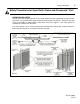
Installation POST MOUNTING: SL580 ONLY 1 Locate and secure two posts, 3” O.D. heavy wall pipe. 2 Remove the mounting angles from base of power unit. Use the angles to maintain the proper distance between posts. Secure the angles to the posts using Ubolts. 3 REAR OF GATE OR BACKFRAME FENCE LINE 9-1/2” 4-1/2” 24-1/8” 3” O.D. Check that: ü Each post is the same distance from the gate. ü That the distance between the posts is 24-1/8”. ü The post height is at least 15” from the ground. 15” MIN.
Installation Step 2: Mounting the Operator For all mounting styles, it is very important that the operator is level and parallel to the gate. PAD MOUNT DETAIL GATE PAD MOUNT: SL580 ONLY After concrete has set, carefully secure operator to the concrete pad with drive and idler sprockets facing gate. The ½” L-bolts will protrude through the holes in the mounting flanges and should be secured with lockwashers and hex nuts (not provided).
Installation Drive Chain Step 4: 1 If you have not already done so, remove the operator cover. 2 Locate and engage the manual disconnect lever and lock it in place. Refer to 14. 3 Connect one chain take-up bolt to the end of the chain and attach to the rear gate bracket. Refer to bracket detail below. 4 Ensure that the drive and idler sprockets are in-line with each other.
Installation 21 BEFORE PROCEEDING PLEASE READ THIS Electrical Disconnect Switch Throughout the course of installation you will be required to disconnect electrical power. This can be done by locating the electrical power disconnect switch and turning it on or off as desired.
Installation Limit Switch Adjustments Step 6: 1 By using the mechanical disconnect, manually open the gate to its full open position (Note direction of limit nut travel). 2 Remove control panel cover and locate the rotary limit switch assembly. Disengage the retaining bracket from the limit nuts. 3 Depending on the “hand” of the operator, rotate the open limit nut until it makes contact with the open limit switch lever and trips the open limit switch activation button.
Programming Programming 01-G0610F13 Figure 21 Switch #1: Operator Programming POLE #1: SINGLE/CLOSE BUTTON ON = Close button only OFF = Open/Close button POLE #2: RIGHT HAND / LEFT HAND ON = Left Hand (gate will open to the left) OFF = Right Hand (gate will open to the right—inside of fence looking out) POLE #3: WARNING DEVICE Figure 22 ON = Warning device will turn on 3 seconds before gate starts to move in either direction. OFF = Warning device disabled.
Programming POLE #1 POLE #2 POLE #3 POLE #4 ON OFF ON OFF ON OFF ON OFF ON OFF ON OFF ON OFF ON OFF ON ON OFF OFF ON ON OFF OFF ON ON OFF OFF ON ON OFF OFF ON ON ON ON OFF OFF OFF OFF ON ON ON ON OFF OFF OFF OFF ON ON ON ON ON ON ON ON OFF OFF OFF OFF OFF OFF OFF OFF TOTAL TIME WARNING DEVICE DISABLED DISABLED 1 SEC. 13 SEC. 26 SEC. 40 SEC. 52 SEC. 65 SEC. 78 SEC. 104 SEC. 117 SEC. 129 SEC. 141 SEC. 155 SEC. 167 SEC. 180 SEC. 194 SEC. TOTAL TIME WARNING DEVICE ENABLED DISABLED 4 SEC. 16 SEC.
Adjustments and Check Out Adjustments and Check Out Clutch Adjustment An adjustable friction type clutch is standard on the models SL580 and SL590. It is important that you properly adjust the clutch to obtain proper operator performance. 1 Loosen the 3 set screws on the clutch nut. 2 Back off the clutch nut until there is very little tension on the clutch spring.
Controls and Accessory Installation 26 Controls and Accessory Installation See wiring diagram for more information. See p. 11 for wiring distances and wire gauge information. All inputs are normally open and momentary, except the stop (NC), and emergency close and emergency open (constant pressure). The following instructions are based upon UL 325, dated March of 1999 and include recommendations for significant increase in safety.
Troubleshooting Troubleshooting When troubleshooting, one of the first things to do is try to isolate the problem area. The four (4) main areas to check out are: Power Accessories Operator’s Primary Voltage Operator’s Low Voltage 1. Power Always use extreme caution! Some possible symptoms of power problems include: The obvious one is – the operator will not run. The operator runs slow. Circuit breakers or fuses keep tripping. Motor overload keeps tripping. Operator starts but then stops 1A.
Troubleshooting 2. Accessories Add-on accessories can create many of the problems that are credited to the operator. Many applications have more than one accessory item attached to the operator and some of these items even draw their power from the operator. Some of the symptoms that can show up because of accessories: The operator won’t close. The operator won’t open. The operator will not run. The operator begins to run then stops or reverses. 2A.
Troubleshooting 29 3B. If there is power, then check for it at the transformer primary terminals. If there is voltage at the switch and none at the transformer, then you probably have a bad power disconnect and it should be replaced. 3C. If 3A and 3B check out O.K., then manually disconnect the operator from the gate. Very carefully, using a screwdriver with an insulated handle, press down on the open side of the contactor. Then, do the same to the close side of the contactor.
Troubleshooting 4E. The R.P.M. Sensor is counting the r.p.m ‘s of the wheel that is attached to the shaft. There are no repairable parts for the sensor of wheel. The only thing that should be checked is the wire harness. Make sure that the wires are crimpled and fully seated into the housing. Also make sure that the housing is fully seated into the circuit board. 4F. The circuit board is the “brains” of the entire system. It is a non-repairable item.
Required Maintenance – Normal Usage Required Maintenance – Normal Usage Check at least once every 1 3 6 12 month months months months Internal speed sensor External safety systems á Check for proper operation á Gate caution signs Make sure they are present á Clutch systemá Brake system Manual disconnect Check & adjust if required Check & adjust if required Check & operate Drive chain (D) (E) Check for excessive slack & lubricate á Sprockets & pulleys Check for excessive slack & lubricate
SL580/590 Parts List & Drawings 32 SL580/590 Parts List & Drawings SL580 Exploded View Figure 28 Doc 01-G0547 Rev D
SL580/590 Parts List & Drawings 33 SL580 Parts List Part No. Qty. Description Part No. Qty. Description Part No. 02-401-SP (N) 03-8024 03-ABDIN-4 07-10179 1 1 1 1 STOP BUTTON 24V REVER. CONTACT. DIN RAIL BRAKE HUB 15-9020 18-10036 (N) 18-10194 18-10467 2 2 4 1 50B12 SPROCKET DEPRESS PLATE SPRING .875L COMPRESS. SPRING COMPRESSION SPRING 82-HN38-16 (N) 82-HN38-18 (N) 82-HW25-06T (N) 82-HX10-08T (N) Qty.
SL580/590 Parts List & Drawings Variable P/N SL580 Variable Parts Description Used On 20-XXXX 20-1050-T 20-1075-T 20-1100-T 20-3050-T 20-3075C-4T 20-3100M-5T 20-3100-T 20-3200-5T 20-3200C-4T 21-3260 21-10298 22-120 22-240 22-575-1 23-3001 23-3005 24-115-1 24-230-5 25-2006 25-2008 25-2010 25-2015 25-2020 25-2025 25-4002-5 25-4004 25-4006 25-4008 MOTOR: 1/2 HP - 115/230VAC - 1Ø - 60hz MOTOR: 3/4 HP - 115/230VAC - 1Ø - 60hz MOTOR: 1 HP - 115/230VAC - 1Ø - 60hz MOTOR: 1/2 HP - 208/230/460VAC - 3Ø - 60
SL580/590 Parts List & Drawings 35 SL590 Exploded View Figure 29 Doc 01-G0547 Rev D
SL580/590 Parts List & Drawings SL590 Parts List Part No. Qty. 02-401-SP (N) 1 Description Part No. Qty. Description Part No.
SL580/590 Parts List & Drawings Variable P/N SL590 Variable Parts Description Used On 20-XXXX 20-1050C-2 20-1075C-2 20-1100 20-1150C-2 20-3050C-4 20-3075C-4 20-3075M-5 20-3100C-4 20-3100M-5 MOTOR: 1/2 HP - 115/208/230VAC - 1Ø - 60hz MOTOR: 3/4 HP - 115/208/230VAC - 1Ø - 60hz MOTOR: 1 HP - 115/208/230VAC - 1Ø - 60hz MOTOR: 1-1/2 HP - 115/208/230VAC - 1Ø - 60hz MOTOR: 1/2 HP - 208/230/460VAC - 3Ø - 60hz MOTOR: 3/4 HP - 208/230/460VAC - 3Ø - 60hz MOTOR: 3/4 HP - 575VAC - 3Ø - 60hz MOTOR: 1 HP - 208/230/4
Warranty Policy 38 Warranty Policy Seller warrants that the goods are free from defect in materials and/or workmanship for a period of one year from the date of shipment from the F.O.B. point. Goods returned to Seller for warranty repair within the warranty period, which upon receipt by Seller are confirmed to be defective and covered by this limited warranty, will be repaired or replaced (at Seller’s sole option) at no cost and returned prepaid.
COPYRIGHT 2001 ALL RIGHTS RESERVED This document is protected by copyright and may not be copied or adapted without the prior written consent of LiftMaster. This documentation contains information proprietary to LiftMaster and such information may not be distributed without the prior written consent of LiftMaster. The software and firmware included in the LiftMaster product as they relate to this documentation are also protected by copyright and contain information proprietary to LiftMaster.