
Safety Gate User Manual

13
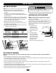
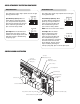
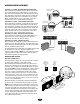
ADJUSTMENT
NOTE: Make sure the limit nuts are positioned between the limit
switch actuators before proceeding with adjustments.
1. Remove control panel cover and locate the limit switch
assembly.
2. Disengage the unit’s manual disconnect (page 12), then
manually open the gate to its full open position (Note direction
of limit nut travel).
3. Adjust the open limit nut by depressing the retaining bracket
to allow nut to spin freely. Adjust open limit nut so that it trips
the open limit switch. After adjustment, release plate and
ensure it seats fully in slots of both nuts.
4. Manually close the gate to its full closed position.
5. Disengage the retaining bracket and rotate the close limit nut
until it trips the close limit switch.
6. Re-engage the retaining bracket into both limit nuts and also
re-engage the manual disconnect.
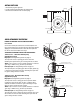
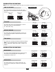
DIRECTION OF
GATE TO OPEN
RIGHT
(Factory Default)
LEFT
OPEN
LIMIT
A
B
CLOSE
LIMIT
B
A
LIMIT SWITCH ADJUSTMENT
LIMIT DIRECTION
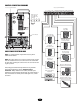
Limit Switch
Limit Switch
Depressed Plate
Retaining
Bracket
Each Notch of the Nut Indicates an
Estimated 1" (2.5 cm) of Gate Travel
Limit Nut A
Limit Nut B
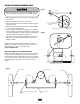
To reduce the risk of SEVERE INJURY or DEATH:
• Disconnect power BEFORE performing ANY adjustments.
WARNING
CAUTION
WARNING
WARNING
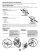
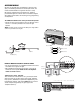
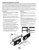
RPM SENSOR (HALL EFFECT) ADJUSTMENT
NOTE: Normally the RPM Sensor (hall effect) does not need
adjustment, but may go out of alignment due to shipping
vibration or rough handling.
These operators use an internal entrapment protector system.
This system consists of the control board, magnet, and
RPM sensor (hall effect). It may become necessary to adjust the
sensor for correct alignment. To do so please perform the
following steps:
1. The sensor must be
centered over the
magnet wheel. Adjust
with horizontal screws.
2. The sensor must be
level.
3. The sensor air gap
should be adjusted to
.010 - .015 of an inch
(.25 - .38 mm). (The
thickness of a business
card may be used to
gauge the correct
distance). Adjust with vertical screws.
Vertical Adjustment
Screws
Horizontal Adjustment
Screws
Magnet
RPM Sensor (Hall Effect)
.010 - .015"
(.25 - .38 mm)
Air Gap
GATE SYSTEM TEST PROCEDURES
Make sure that the gate’s path is clear from any obstructions and that all associated gate hardware is properly mounted and
secured.
1. With the power off, manually move the gate to the fully closed position.
2. At the closed position, turn the power on and observe the GL controller board’s diagnostic and limit LEDs. When power is turned on,
these LEDs should flash simultaneously for a few seconds.
3. Locate the 3-button control that is built into the electrical box.
4. Push the open button and observe the operator’s behavior. The gate should begin opening. If the operator fails to open or has
difficulty opening, refer to the troubleshooting section.
5. Once at the open limit, the gate will stop. Push the close button and observe the operator’s behavior. If the operator fails to close or
has difficulty closing, refer to the troubleshooting section.
6. While the gate is closing, push the stop button. The gate should now stop.
7. Push the close button to return the gate to the fully closed position.