
Manual

4
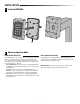
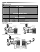
WIRING
Red
Black
Normally Open
Blue
Purple
Gray
Pink
Install a 1N4007 or
equivalent diode.
Common
(1 Amp Maximum)
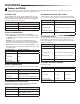
Wire Insulation Color Wiring Function Notes
Basic Stand Alone Wiring
Red Power + 12~24 Volts DC Regulated Power Input
Black Power - 12~24 Volts DC Regulated Power Input
Pink Power - Ground Conductor
Blue Relay NO Normally Open Relay Output (Install diode provided)
Purple Relay Common Common Connection for Relay Output
Orange Relay NC Normally Closed Relay Output (Install diode provided)
Pass-Through Wiring (Wiegand Master and Remote)
Green Data 0 Wiegand Output (Pass-through)/Input (Stand Alone) Data 0
White Data 1 Wiegand Output (Pass-through)/Input (Stand Alone) Data 1
Pink Ground
Advanced Input and Output Features
Yellow REX Request To Exit (REX) Input
Gray Alarm Output Negative contact for Alarm
Brown Contact Input Door/Gate Contact Input (Normally Closed)
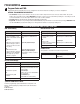
Gate/Door Operator or Fail-Secure Strike
Red
Black
Pink
Orange
Purple
Normally Closed
Install a 1N4007 or
equivalent diode.
Common
Gray
(1 Amp Maximum)
Magnetic Lock or Fail-Safe Strike
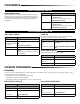
KPR2000
External AlarmExternal Alarm
External Alarm
KPR2000
Green (Data 0)
White (Data 1)
Pink (must connect for ground reference)
Maximum of 500 feet (152.4 m)
Red
Black
Normally Open
Blue
Purple
Gray
Pink
Install a 1N4007 or
equivalent diode.
Common
(1 Amp Maximum)
Black
Pink
Red
Networking Two KPR2000 Units or Connecting to an Access Control System
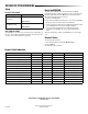
3
Wire the KPR2000.
WIRING EXAMPLES:
KPR2000 Stand-Alone
(Master Unit)
KPR2000 Stand-Alone
(Remote Unit)