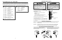
MGJ CONTROL CONNECTION DIAGRAM (Refer to page 15 for model LGJ control connections) IMPORTANT NOTES: ATTENTION ELECTRICIAN: 1) The 3-Button Control Station provided must be connected for operation. USE 16 GAUGE OR HEAVIER WIRE 2) If a STOP button is not used, a jumper must be placed between termianls 3 and 4. FOR ALL CONTROL CIRCUIT WIRING. 3) Auxiliary control equipment may be any normally open two wire device such as pullswitch, single button, loop detector, card key or such device.
ILLUSTRATED PARTS – MODEL MGJ SPECIFICATIONS MOTOR ELECTRICAL TRANSFORMER:.............24VAC HORSEPOWER: ................MGJ: 1/2Hp 1 or 3 Phase LGJ: 1/4 Hp 1 Phase CONTROL STATION: ......NEMA 1 three button station. OPEN/CLOSE/STOP D11 D2 D13 D14 D3 CURRENT: See motor nameplate D15 SPEED:...............................MGJ: 1050 RPM WIRING TYPE: MGJ: B2-C2 (Factory Shipped) LGJ: 1725 RPM LGJ: G2 (Factory Shipped) VOLTAGE: ..........................
IMPORTANT SAFETY NOTES REPLACEMENT PART LISTS – MODEL MGJ Refer to the parts lists below for replacement kits available for your operator. If optional modifications and/or accessories are included with your operator, certain components may be added or removed from these lists. Individual components of each kit may not be available. Please consult a parts and service representative regarding availability of individual components. Refer to page 10 for all repair part ordering information.
MGJ ELECTRICAL BOX - ILLUSTRATED PARTS 2. Re-assemble Disconnect Assembly Remove the two screws on the opposite side of the gear reducer and mount the disconnect support bracket with the notched side facing the motor. For the remainder of the installation, follow the steps outlined above in reverse order, referring to the illustration as necessary. Remove the three cotter pins from the disconnect shaft. Do not discard the pins. Slide the disconnect shaft out of the support bracket.
REPLACEMENT PART KITS MGJ Below are replacement kits available for your operator. For replacement of electrical box, motor or brake components be sure to match model number of your unit to kit number below to ensure proper voltage requirements. Optional modifications and/or accessories included with your operator may add or remove certain components from these lists. Please consult a parts and service representative regarding availability of individual components of kits specified below.
OPERATOR MOUNTING LGJ ILLUSTRATED PARTS Before your operator is installed, be sure the door has been properly aligned and is working smoothly. The operator may be wall mounted or mounted on a bracket or shelf. If necessary, refer to the operator preparations on page 3. Refer to the illustration and instructions below that suits your application. 1a. Wall Mounting The operator should generally be installed below the door shaft, and as close to the door as possible.
REPLACEMENT PART LISTS – MODEL LGJ Refer to the parts lists below for replacement kits available for your operator. If optional modifications and/or accessories are included with your operator, certain components may be added or removed from these lists. Individual components of each kit may not be available. Please consult a parts and service representative regarding availability of individual components. Refer to page 10 for all repair part ordering information.
ENTRAPMENT PROTECTION ACCESSORIES (OPTIONAL) LGJ ELECTRICAL BOX - ILLUSTRATED PARTS SENSING EDGES All types of sensing edges with an isolated normally open (N.O.) output are compatible with your operator. This includes pneumatic and electric edges. If your door does not have a bottom sensing edge and you wish to purchase one, contact the supplier of your operator. IT IS STRONGLY RECOMMENDED THAT A SENSING EDGE OR OTHER ENTRAPMENT PROTECTION DEVICE BE USED IN CONJUNCTION WITH THIS OPERATOR.
REPLACEMENT PART KITS LGJ Below are replacement kits available for your operator. Optional modifications and/or accessories included with your operator may add or remove certain components from these lists. Please consult a parts and service representative regarding availability of individual components of kits specified below. Refer to page 10 for all repair part ordering information.
MAINTENANCE SCHEDULE LGJ CONTROL CONNECTION DIAGRAM 41B6 Check at the intervals listed in the following chart. LISTED DOOR OPERATOR ITEM Drive Chain PROCEDURE Check for excessive slack. Check & adjust as required. Lubricate.
SINGLE PHASE SCHEMATIC DIAGRAM for LGJ 1666 CONTROL WIRING DETERMINE WIRING TYPE Refer to the wiring diagram located on the inside cover the electrical box to determine the type of control wiring. MODEL MGJ MODEL LGJ Standard C2 or B2 Wiring Model MGJ operators are shipped from the factory with jumper set for C2 wiring, which requires constant pressure on button to close the door. If momentary contact in close direction is desired (B2 wiring) you must include an entrapment protection device.
SINGLE PHASE SCHEMATIC DIAGRAM for MGJ THREE PHASE SCHEMATIC DIAGRAM for MGJ 1754 (OPTIONAL) (OPTIONAL) BIMETAL RELAY C MAX. 100W B BL/BK BRN BK A WIRE NUT CLOSE-B 1 7 4 2 8 5 YEL 3 9 6 BRN W O/L* BL/BK 7 4 8 5 YEL 3 9 6 O/L* BRN BL/BK 460 VOLT - 3 PHASE MOTOR CONNECTION (GY) RES.
SINGLE PHASE SCHEMATIC DIAGRAM for MGJ THREE PHASE SCHEMATIC DIAGRAM for MGJ 1754 (OPTIONAL) (OPTIONAL) BIMETAL RELAY C MAX. 100W B BL/BK BRN BK A WIRE NUT CLOSE-B 1 7 4 2 8 5 YEL 3 9 6 BRN W O/L* BL/BK 7 4 8 5 YEL 3 9 6 O/L* BRN BL/BK 460 VOLT - 3 PHASE MOTOR CONNECTION (GY) RES.
SINGLE PHASE SCHEMATIC DIAGRAM for LGJ 1666 CONTROL WIRING DETERMINE WIRING TYPE Refer to the wiring diagram located on the inside cover the electrical box to determine the type of control wiring. MODEL MGJ MODEL LGJ Standard C2 or B2 Wiring Model MGJ operators are shipped from the factory with jumper set for C2 wiring, which requires constant pressure on button to close the door. If momentary contact in close direction is desired (B2 wiring) you must include an entrapment protection device.
MAINTENANCE SCHEDULE LGJ CONTROL CONNECTION DIAGRAM 41B6 Check at the intervals listed in the following chart. LISTED DOOR OPERATOR ITEM Drive Chain PROCEDURE Check for excessive slack. Check & adjust as required. Lubricate.
REPLACEMENT PART KITS LGJ LGJ LIMIT SWITCH ADJUSTMENT Below are replacement kits available for your operator. Optional modifications and/or accessories included with your operator may add or remove certain components from these lists. Please consult a parts and service representative regarding availability of individual components of kits specified below. Refer to page 10 for all repair part ordering information.
ENTRAPMENT PROTECTION ACCESSORIES (OPTIONAL) LGJ ELECTRICAL BOX - ILLUSTRATED PARTS SENSING EDGES All types of sensing edges with an isolated normally open (N.O.) output are compatible with your operator. This includes pneumatic and electric edges. If your door does not have a bottom sensing edge and you wish to purchase one, contact the supplier of your operator. IT IS STRONGLY RECOMMENDED THAT A SENSING EDGE OR OTHER ENTRAPMENT PROTECTION DEVICE BE USED IN CONJUNCTION WITH THIS OPERATOR.
REPLACEMENT PART LISTS – MODEL LGJ Refer to the parts lists below for replacement kits available for your operator. If optional modifications and/or accessories are included with your operator, certain components may be added or removed from these lists. Individual components of each kit may not be available. Please consult a parts and service representative regarding availability of individual components. Refer to page 10 for all repair part ordering information.
OPERATOR MOUNTING LGJ ILLUSTRATED PARTS Before your operator is installed, be sure the door has been properly aligned and is working smoothly. The operator may be wall mounted or mounted on a bracket or shelf. If necessary, refer to the operator preparations on page 3. Refer to the illustration and instructions below that suits your application. 1a. Wall Mounting The operator should generally be installed below the door shaft, and as close to the door as possible.
REPLACEMENT PART KITS MGJ Below are replacement kits available for your operator. For replacement of electrical box, motor or brake components be sure to match model number of your unit to kit number below to ensure proper voltage requirements. Optional modifications and/or accessories included with your operator may add or remove certain components from these lists. Please consult a parts and service representative regarding availability of individual components of kits specified below.
MGJ ELECTRICAL BOX - ILLUSTRATED PARTS 2. Re-assemble Disconnect Assembly Remove the two screws on the opposite side of the gear reducer and mount the disconnect support bracket with the notched side facing the motor. For the remainder of the installation, follow the steps outlined above in reverse order, referring to the illustration as necessary. Remove the three cotter pins from the disconnect shaft. Do not discard the pins. Slide the disconnect shaft out of the support bracket.
IMPORTANT SAFETY NOTES REPLACEMENT PART LISTS – MODEL MGJ Refer to the parts lists below for replacement kits available for your operator. If optional modifications and/or accessories are included with your operator, certain components may be added or removed from these lists. Individual components of each kit may not be available. Please consult a parts and service representative regarding availability of individual components. Refer to page 10 for all repair part ordering information.
ILLUSTRATED PARTS – MODEL MGJ SPECIFICATIONS MOTOR ELECTRICAL TRANSFORMER:.............24VAC HORSEPOWER: ................MGJ: 1/2Hp 1 or 3 Phase LGJ: 1/4 Hp 1 Phase CONTROL STATION: ......NEMA 1 three button station. OPEN/CLOSE/STOP D11 D2 D13 D14 D3 CURRENT: See motor nameplate D15 SPEED:...............................MGJ: 1050 RPM WIRING TYPE: MGJ: B2-C2 (Factory Shipped) LGJ: 1725 RPM LGJ: G2 (Factory Shipped) VOLTAGE: ..........................
MGJ CONTROL CONNECTION DIAGRAM (Refer to page 15 for model LGJ control connections) IMPORTANT NOTES: ATTENTION ELECTRICIAN: 1) The 3-Button Control Station provided must be connected for operation. USE 16 GAUGE OR HEAVIER WIRE 2) If a STOP button is not used, a jumper must be placed between termianls 3 and 4. FOR ALL CONTROL CIRCUIT WIRING. 3) Auxiliary control equipment may be any normally open two wire device such as pullswitch, single button, loop detector, card key or such device.