
Owner's Manual


22
3
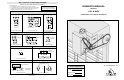
2-1/4"
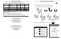
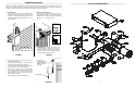
FIGURE 1
Shaft Support Bracket
with Bearing (Not Supplied)
Door Sprocket
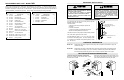
TO AVOID DAMAGE TO DOOR AND OPERATOR,
MAKE ALL DOOR LOCKS INOPERATIVE. SECURE
LOCK(S) IN "OPEN" POSITION.
IF THE DOOR LOCK NEEDS TO REMAIN
FUNCTIONAL, INSTALL AN INTERLOCK SWITCH.
DO NOT CONNECT ELECTRIC POWER UNTIL
INSTRUCTED TO DO SO.
KEEP DOOR BALANCED. STICKING OR BINDING
DOORS MUST BE REPAIRED. DOORS, DOOR
SPRINGS, CABLES, PULLEYS, BRACKETS AND
THEIR HARDWARE MAY BE UNDER EXTREME
TENSION AND CAN CAUSE SERIOUS PERSONAL
INJURY. CALL A PROFESSIONAL DOOR
SERVICEMAN TO MOVE OR ADJUST DOOR
SPRINGS OR HARDWARE.
WARNING
CAUTION
CAUTION
WARNING
WARNING
WARNING
CAUTION
WARNING
WARNING
SITE PREPARATIONS
It is imperative that the wall or mounting surface provide
adequate support for the operator.
This surface must:
a) Be rigid to prevent play between operator and
door shaft.
b) Provide a level base.
c) Permit the operator to be fastened securely and
with the drive shaft parallel to the door shaft.
The safety and wear of the operator will be adversely affected
if any of the above requirements are not met.
For metal buildings, fasten 2” x 2” x 3/16” (or larger) angle
iron frames to the building purlins. For proper spacing, retain
.2.75” between for model MGJ, butt purlins together for model
LGJ. See Figure 1.
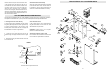
OPERATOR PREPARATION
IMPORTANT SAFETY NOTES
2.75 for MGJ, butt together for LGJ
Model LGJ: Shipped from the factory for right hand mounting, refer to preparation instructions on page 4 for
Left hand mounting.
Model MGJ: Shipped from the factory for either left hand or right hand mounting. Refer to the last digit in the
model number for handing of your unit. If necessary, model MGJ may also be field modified to
accommodate opposite handing. Refer to the conversion instructions below and on page 4.
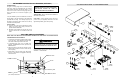
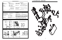
REPLACEMENT PART LISTS – MODEL MGJ
Refer to the parts lists below for replacement kits available for your operator. If optional modifications and/or
accessories are included with your operator, certain components may be added or removed from these lists.
Individual components of each kit may not be available. Please consult a parts and service representative
regarding availability of individual components. Refer to page 10 for all repair part ordering information.
K75-12567 DISCONNECT ASSEMBLY KIT
ITEM PART # DESCRIPTION QTY
D1
D2
D3
D4
D5
D6
D7
D8
D9
D10
D11
D12
D13
D14
D15
Disconnect Hub
Bevel Gear Yoke
Disconnect Support Bracket
Release Lever
Disconnect Shaft MGJ
Sprocket, 41B19 x 1.25 Bore
Compression Spring
12ft. Of Sash Chain
Disconnect Key 1/4 x 1/4 x 7/8
Washer, 1” I.D. x 1/16” Thick
Screw, #10-32 Hex Head Socket
#10 Lock Washer ZP
Cotter Pin, 1/8” x 1-3/4” Long
Roll Pin, 1/8” Dia. x 1” Long
E Ring, 1” Plated
1
1
1
1
1
1
1
1
2
1
2
2
4
1
2
07-11418
10-11023
10-11358
10-11394
11-11361
15-11377
18-10467
19-8A-12
80-11416
80-206-11
82-SH10-12
85-LS-10
86-CP04-112
86-RP04-100
87-E-100
INDIVIDUAL PARTS
ITEM PART # DESCRIPTION QTY
1
2
3
4
5
Brake Mounting Plate
Front Bracket
Gear Reducer, 45:1
Electrical Box
Motor
1
1
1
1
1
10-11357
10-11359
32-11414
See Page 20
See Page 20
KEYS
SPRING
DISC
HUB
E RING
SPROCKET
YOKE
BRACKET
SHAFT
DISC
LEVER
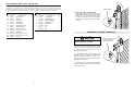
MGJ OPPOSITE HANDING PREPARATIONS
1. Remove Disconnect Assembly Components
Remove the master link from the limit chain, remove
the chain and set it aside.
Remove the two E Rings securing the sprocket on the
gear reducer shaft. Remove the screws securing the
yoke to the disconnect shaft, set the yoke aside.