
Owner's Manual


16
9
REPLACEMENT PART KITS LGJ
SOLID STATE
Item P/N Description QTY
Below are replacement kits available for your operator. Optional modifications and/or accessories included with
your operator may add or remove certain components from these lists. Please consult a parts and service
representative regarding availability of individual components of kits specified below. Refer to page 10 for all
repair part ordering information.
K72-12581 LIMIT SHAFT ASSEMBLY KIT
Item
L1
L2
L3
L4
L5
L6
L7
L8
L9
L10
Description
Limit Shaft
3/8” Bearing, Plastic Flange
Limit Nut
Sprocket, 48B07
Rotor for RSL Assembly
Washer, Shim
Washer, Shim
Washer, Shim
Roll Pin, 1/8” Dia. x 3/4” Long
E Ring, 3/8”
Qty
1
2
2
1
1
1
1
1
1
3
K75-12582 LIMIT SWITCH ASSEMBLY KIT
Complete Electrical Box Replacement Kit
K-LGJ2511 Model LGJ2511
Electrical Box Sub-Assembly Kits
K72-12581 LGJ Limit Shaft Assembly
K75-12582 LGJ Limit Switch Assembly
K79-11384 LGJ PC Board Assembly
P/N
11-11425
12-10458
13-10024
15-48B07AXX
81-11443
80-10053
80-10025
80-10026
86-RP04-012
87-E-038
Item
S1
S2
S3
S4
S5
S6
S7
S8
Description
Depress Plate
Spring, Depress Plate
Limit Switch
Limit Switch
Standoff, #4-40 Threaded x .19 Long
Screw, #4-40 x 1” Pan Head Ph
Screw, #6-32 x 1” Pan Head Ph
Locknut #6-32
Qty
1
2
2
2
4
4
2
2
P/N
10-11391
18-10036
23-10041
23-11442
80-11445
82-PX04-16
82-PX06-16
84-LH-06
10-11390M1
10-11392M1
21-13395
29-7642
42-9306
42-13378
75-11395
79-11378
80-10027
11-11425
12-10458
13-10024
15-48B07AXX
81-11443
85-FW-38
86-RP04-012
87-E-038
10-11391
18-10036
23-10041
23-11442
80-11446
82-PX04-16
82-PX06-16
84-LH-06
1
2
3
4
5
6
7
8
9
L1
L2
L3
L4
L5
L6
L7
L8
S1
S2
S3
S4
S5
S6
S7
S8
1
1
1
1
1
1
1
1
4
1
2
2
1
1
4
1
1
1
2
2
2
4
4
2
2
Electrical Box Cover
Electrical Box
Transformer, LGJ 115V-24VAC
Capacitor 220V 42MFD
Terminal Block 6 Pole
J2 Terminal Block, 16 Pole (1-16)
Hall Effect Assembly
PCB Board Assembly
PCB Board Standoff
Limit Shaft
3/8” Bearing, Plastic Flange
Limit Nut
Sprocket, 48B07
Rotor for RSL Assembly
Flat Washer, 3/8”
Roll Pin, 1/8” Dia. x 3/4” Long
E Ring, 3/8”
Depress Plate
Spring, Depress Plate
Limit Switch
Limit Switch
Standoff, #4-40 Threaded x .19 Long
Screw, #4-40 x 1” Pan Head Ph
Screw, #6-32 x 1” Pan Head Ph
Locknut #6-32
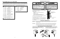
LGJ LIMIT SWITCH ADJUSTMENT
IMPORTANT NOTE: To avoid danger of possible damage to the door and operator, limit switches must be
adjusted to their approximate positions before applying power to the operator.
NEVER PLACE HANDS OR TOOLS INSIDE
OPERATOR OR NEAR MECHANISM UNLESS
POWER IS OFF!!
WARNING
CAUTION
WARNING
WARNING
A. Set Limit Direction Switch
Open the cover on the electrical enclosure and locate
dip switch SW1 on circuit board. The direction of the
limit travel is determined by the switch SW1 - pole #2
setting.
If your operator is mounted Motor Side Up:
Set dip switch SW1 - pole #2 to “ON” position.
If your operator is mounted Motor Side Down:
Set dip switch SW1 - pole #2 to “OFF” position.
NOTE: See Mounting Options on page 5 to verify the
correct mounting application.
As determined by SW1 - pole 2 setting above, locate
your OPEN and CLOSE limit switches. See the figure
below for switch layout.
For Motor Side Up Mounting: Limit switch -A- is the
OPEN limit. Limit switch -B- is the CLOSE limit.
For Motor Side Down Mounting: Limit switch -A- is
the CLOSE limit. Limit switch -B- is the OPEN limit.
Auxiliary limit switches to control other functions are
also present and should not be confused with the -A-
and -B- limit switches. There are two(2) limit nuts on
the threaded shaft that transverse the shaft as the
operator opens and closes the door. When a limit nut
nears the end of the shaft, it activates a switch(es).
B. Manually raise the door to a nearly open position.
(see page 17, Manual Operation)
C. Depress the limit nut retaining bracket away from
the slots in the limit nuts, and manually rotate to the
OPEN limit nut until it depresses the OPEN limit
switch lever (you can hear the switch click when the
switch contacts transfer). Release the retaining
bracket and be sure it engages in the slots of both
limit nuts.
D. Manually lower the door to a nearly closed
position, and repeat step C with the CLOSE (right)
limit nut.
E. Test Limit Travel
Manually move the door to a half-open position to
avoid damage due to incorrect (dip switch setting)
limit travel. When power is applied, it will cause the
door to OPEN when the limit nuts are traveling in the
direction of the CLOSE limit switch or vice versa. In
either instance, the limit nuts will travel past the limit
switch and may cause damage to both the door and
operator. See Step A for correct setting.
F. After completing the wiring connections on pages
11 thru 13, refer back to step C above for adjustment
of limit switches to their final, exact position.
Limit Switch -A-
(Top Switch)
Dip Switch
SW1
Limit Switch -B-
(Top Switch)
Limit Nut
Limit Switch -A-
(Bottom Switch)
Limit Switch -B-
(Bottom Switch)
If you operator is mounted Motor
Side Up: Set dip switch SW1 - pole
#2 to “ON” position
If your operator is mounted
Motor Side Down: Set dip switch
SW1 - pole #2 to “OFF” position.
When SW1 - pole 2 position is
“ON”: Limit switch -A- is the OPEN
limit. Limit switch -B- is the close
limit.
When SW1 - pole 2 position is
“OFF”: Limit switch -A- is the
CLOSE limit. Limit Switch -B- is the
OPEN limit.
Limit Switch Layout
COMPLETE ELECTRICAL BOX KITS
Motor Kit
K20-1025C1 Model LGJ2511
Disconnect Assembly Kit
K75-12583 Model LGJ2511