TABLE OF CONTENTS SAFETY 1 OPERATION SAFETY SYMBOL AND SIGNAL WORD REVIEW .....................................1 USAGE CLASS ..........................................................................................2 UL325 ENTRAPMENT PROTECTION REQUIREMENTS .............................2 SAFETY INSTALLATION INFORMATION ...................................................3 GATE CONSTRUCTION INFORMATION .....................................................4 INTRODUCTION 31 CONTROL BOARD OVERVIEW ........
SAFETY USAGE CLASS CLASS I – RESIDENTIAL VEHICULAR GATE OPERATOR I A vehicular gate operator (or system) intended for use in garages or parking areas associated with a residence of one-to four single families.
SAFETY SAFETY INSTALLATION INFORMATION 1. Vehicular gate systems provide convenience and security. Gate systems are comprised of many component parts. The gate operator is only one component. Each gate system is specifically designed for an individual application. 2. Gate operating system designers, installers and users must take into account the possible hazards associated with each individual application.
SAFETY GATE CONSTRUCTION INFORMATION Vehicular gates should be installed in accordance with ASTM F2200: Standard Specification for Automated Vehicular Gate Construction. For a copy, contact ASTM directly at 610-832-9585 or www.astm.org. 1. GENERAL REQUIREMENTS 1.1 Gates shall be constructed in accordance with the provisions given for the appropriate gate type listed, refer to ASTM F2200 for additional gate types. 1.
INTRODUCTION CARTON INVENTORY NOT SHOWN: Documentation packet and hardware bag LA412DCS ONLY Pull-to-Open Bracket Wire Nuts (6) Post Bracket Pull-to-Open Bracket Watertight Connector (2) Post Bracket Standard Control Box with 2 Batteries Gate Bracket 12V 10W Solar Panel Model SOLPNL10W12V (1) Gate Bracket Connector Junction Box Cable Ties (4) Gate Operator Gate Operator Warning Signs (2) Extension Cable HARDWARE INVENTORY NOTE: Hardware quantities shown below are for LA412DC.
INTRODUCTION SPECIFICATIONS This model is intended for use in vehicular swing gate applications: Usage Classification Class I Main AC Supply N/A - Solar Only System Operating Voltage 12 Vdc Battery Run / Solar Charge Accessory Power 12 Vdc, 500mA max for ON + SW (switched) Solar Power Max 12 Vdc at 30 watts max. Maximum Gate Weight/Length 850 lbs. (385.6 kg) / 10 ft (3.0 m) 750 lbs. (340.2 kg) / 12 ft (3.7 m) 650 lbs. (294.8 kg) / 14 ft (4.3 m) 550 lbs. (249.5 kg) / 16 ft (4.
INTRODUCTION SITE PREPARATION Check the national and local building codes BEFORE installation. LOOPS TRENCH Trench and install conduit. Before trenching, contact underground utility locating companies. Conduit must be UL approved for low and high voltage. Loops allow the gate to stay open when vehicles are obstructing the gate path. Suggested for vehicles 14 feet (4.27 m) or longer. Loops are not required but are recommended.
INTRODUCTION OVERVIEW OF TYPICAL INSTALLATION Identify your installation type (refer to the Appendix in the back of the manual for more information). All the illustrations on the following pages display a typical Left-Hand Gate installation with a pull-to-open bracket. For Push-to-Open applications refer to the Appendix.
INSTALLATION IMPORTANT SAFETY INFORMATION To prevent SERIOUS INJURY or DEATH from a moving gate: • Pinch points must be guarded at all times. Install enclosed-style gate tracks and roller guards. • Place screen mesh 6 feet (1.8 m) high on the gate to prevent access through openings anywhere the gate may travel. • Mount controls at least 6 feet (1.8 m) from the gate or ANY moving part of the gate. • Install Warning signs on EACH side of gate in PLAIN VIEW.
INSTALLATION STEP 1 ATTACH BRACKETS TO OPERATOR 1. Insert the key into the lock on the release lever and turn it 180° counterclockwise. 2. Turn the release lever 180° counterclockwise. The operator is now in manual mode. 3. Assemble gate post bracket by placing pull-to-open bracket on top of post bracket. 4. Insert the bolt through both brackets and secure with washer, lock washer and nut. 5. Attach post bracket assembly to operator using pins and hairpin clips. 6.
INSTALLATION STEP 2 DETERMINE MOUNTING LOCATION MEASURING AND MARKING FOR THE GATE BRACKET Before proceeding, begin with the gate in the fully closed position. There are two methods for determining the proper location of the post brackets: • Paper template (Located on the back page of this manual. Must be cut out.) • Tape measure. Either method will work depending on preference. NOTE: There should only be a maximum of 4" (10.2 cm) from the center of the hinge to the edge of the post or column.
INSTALLATION STEP 3 POSITION THE OPERATOR NOTE: The post bracket assembly can be mounted several places on the gate post. 1. Open the gate to desired open position (no greater than 100°) and hold operator against gate. 2. Place the operator arm against gate post at the desired position. Temporarily secure gate post bracket with clamp. The gate operator (arm) must be level. 3. Mark mounting holes on gate for reference. Temporarily secure the gate bracket using a clamp. 4.
INSTALLATION STEP 4 SECURE THE BRACKETS POST BRACKET The gate operator (arm) must be level. 1. Mark holes for the post bracket. Remove the clamp and the operator, set aside. 2. Drill adequate holes in the gate post. 3. Secure the post bracket to the gate post using hardware. GATE BRACKET The gate operator (arm) must be level. Some installations may require additional reinforcement be installed on the gate. 1.
INSTALLATION STEP 5 INSTALL THE CONTROL BOX WALL OR COLUMN MOUNT For Large Metal Control Box installation, refer to the following page. STANDARD CONTROL BOX The control box MUST be mounted within 5 feet (1.52 m) of the gate operator. Mount the control box as high as possible for best radio reception. Make sure the control box is level. 1. Remove the screws and open the control box. 2. Select the mounting holes (according to your application) and remove the knockouts using a screwdriver and hammer. 3.
INSTALLATION STEP 5 continued... INSTALL THE CONTROL BOX WALL OR COLUMN MOUNT LARGE METAL CONTROL BOX (XLSOLARCONTDC) The control box MUST be mounted within 5 feet (1.52 m) of the gate operator. Mount the control box as high as possible for best radio reception. Make sure the control box is level. WALL OR COLUMN MOUNT 1. Open the control box. The control box door may be removed by opening the door 90°. Lift the door from the hinges and set aside until the installation is complete. 2.
INSTALLATION To reduce the risk of SEVERE INJURY or DEATH: • ANY maintenance to the operator or in the area near the operator MUST NOT be performed until disconnecting the electrical power (AC or solar and battery) and locking-out the power via the operator power switch. Upon completion of maintenance the area MUST be cleared and secured, at that time the unit may be returned to service. • Disconnect power at the fuse box BEFORE proceeding.
INSTALLATION STEP 8 DUAL GATES ONLY There are two options for dual gate communication: wired or wireless. Follow the directions according to your application. Do not use wired and wireless communication simultaneously. Wired dual gate applications will have a longer battery standby time than wireless applications. Wireless dual gates will require the installation of two control boxes, one for each operator arm.
INSTALLATION STEP 8 continued... DUAL GATES ONLY WIRED DUAL GATES Brown INSTALL A SECOND OPERATOR ARM Green Install a second operator arm by following installation steps 1-4. Extension Cable White INSTALL THE EXTENSION CABLE AND JUNCTION BOX Operator Cable Yellow Blue Before digging, contact local underground utility locating companies. 1. Trench across driveway to bury the extension cable. Use PVC conduit to prevent damage to cables. 2.
INSTALLATION STEP 8 continued... DUAL GATES ONLY (Control Board) Watertight Connector WIRE THE SECONDARY OPERATOR ARM TO THE CONTROL BOARD 1. Choose a knockout in the bottom of the control box. 2. Insert the extension cable through the watertight connector. 3. Insert the extension cable and watertight connector into the knockout. 4. Slide the connector nut onto the operator cable. 5.
INSTALLATION To prevent SERIOUS INJURY or DEATH from a moving gate: • Entrapment protection devices MUST be installed to protect anyone who may come near a moving gate. • Locate entrapment protection devices to protect in BOTH the open and close gate cycles. • Locate entrapment protection devices to protect between moving gate and RIGID objects, such as posts or walls.
INSTALLATION STEP 9 continued... INSTALL ENTRAPMENT PROTECTION There are three options for wiring the entrapment protection devices depending on the specific device and how the device will function. Refer to the wiring diagram or the specific entrapment protection device manual for more information. These entrapment protection device inputs are for monitored devices, which include pulsed photoelectric sensors, resistive edge sensors, and pulsed edge sensors.
INSTALLATION STEP 10 INSTALL SOLAR PANEL(S) SELECT SITE FOR SOLAR PANEL(S) The solar panel(s) must be located in an open area clear of obstructions and shading for the entire day. The solar panel(s) comes with a 10 foot (3 m) cable. If a location near the control box cannot be found, an additional cable will be required. The LA412DC Solar Gate Operator is not supported in northern climates where temperatures reach below -4° F.
INSTALLATION STEP 10 continued...
INSTALLATION STEP 10 continued... INSTALL SOLAR PANEL(S) The location of the panel(s) is critical to the success of the installation. In general, the panel(s) should be mounted using the provided angle bracket facing due south. Use a compass to determine direction. The solar panel(s) should be mounted in an area clear of all obstructions and shading from buildings and trees. If the panel(s) is not casting a shadow, the battery is not being charged.
INSTALLATION STEP 10 continued... INSTALL SOLAR PANEL(S) INSTALL THE SOLAR PANEL 1. Position solar bracket on mounting surface. Mark and drill holes. 2. Insert two bolts into the track located on the back of the solar panel(s). Mounting Surface 3. Slide bolts in track away from bolt hole and align both bolts. 4. Secure solar panel(s) to solar bracket using two washered nuts. 5. Secure solar panel(s) assembly to mounting surface using appropriate hardware.
INSTALLATION STEP 12 FINISH INSTALL 1. Turn the release lever clockwise 180° back to the engaged position. This engages the motor. The illustration shows the release lever in the engaged position. 2. Turn the key clockwise 180°. This locks the release lever. The operator is now engaged. 3. Fasten warning signs to the gate with cable ties. Warning signs MUST be installed on both sides of the gate and in plain view.
ADJUSTMENT LIMIT AND FORCE ADJUSTMENT continued... For dual gate applications the limits will have to be set for each operator. The gate MUST be attached to the operator before setting the limits and force. INITIAL LIMITS AND FORCE ADJUSTMENT If a mistake is made while programming the limits press the reset button to start over. 1 TIMER TO CLOS PRESS & RELEASE TO BEGIN 1. Set the GATE switch to the 1 position. 2.
ADJUSTMENT LIMIT AND FORCE ADJUSTMENT continued... FINE TUNE THE FORCE NETWORK If the gate stops or reverses before reaching the fully open or closed position, increase the force by turning the force control slightly clockwise. STOP 2. CLOSE Open and close the gate with the test buttons. XMITTER RSAL RCE Based on the length and weight of the gate it may be necessary to make additional force adjustments.
PROGRAMMING REMOTE CONTROLS (NOT PROVIDED) A total of 50 Security✚ 2.0™ remote controls and 2 keyless entries (1 PIN for each keyless entry) can be programmed to the operator. When programming a third keyless entry to the operator, the first keyless entry will be erased to allow the third keyless entry to be programmed. When the operator’s memory is full it will exit the programming mode and the remote control will not be programmed.
PROGRAMMING LIFTMASTER INTERNET GATEWAY (NOT PROVIDED) ERASE ALL CODES 1. Press and release the LEARN button (operator will beep and green XMITTER LED will light). 2. Press and hold the LEARN button again until the green XMITTER LED flashes and then release the button (approximately 6 seconds). All remote control codes are now erased. To program the operator to the LiftMaster Internet Gateway: USING THE LEARN BUTTON ON THE OPERATOR’S CONTROL BOARD 1.
OPERATION CONTROL BOARD OVERVIEW 1 2 3 4 5 6 7 8 9 10 11 SET OPEN Button: The SET OPEN button sets the OPEN limit. See Adjust Limits section. SET CLOSE Button: The SET CLOSE button sets the CLOSE limit. See Adjust Limits section. MOVE GATE Buttons: The MOVE GATE buttons will either open or close the gate when the operator is in Limit setting mode. See Adjust Limits section.
OPERATION MANUAL RELEASE In case of a power failure, the operator can be disengaged from the gate. With an operator, the release action may sometimes feel stiff/jerky, which is normal and has no effect on function. NOTE: It is normal for the operator to run slow right after a disconnect or complete loss of AC/ battery power (the operator will need to run a complete open and close cycle). RELEASE 1. Insert the key into the lock. 2. Turn the key counter-clockwise 180°. 3.
OPERATION OPERATOR ALARM If a contact sensor detects an obstruction twice consecutively the alarm will sound (up to 5 minutes) and the operator will need to be reset. When the inherent force of the operator (RPM/current sensor) detects the following (twice consecutively) the alarm will sound (up to 5 minutes) and the operator will need to be reset: A. The operator arm or gate is incorrectly installed. B. The gate does not meet specifications. A C.
ACCESSORY WIRING EXTERNAL CONTROL DEVICES EXIT (2 Terminals) This input is a soft open command (maintained switch does not override external safeties and does not reset alarm condition). Used for exit probe, telephone entry, external exit loop detector, or any device that would command the gate to open. • (control board) Exit Com Shadow Opens a closing gate and holds open an open gate, if maintained, pauses Timer-to-Close at OPEN limit.
ACCESSORY WIRING LOCKS (control board) MAGLOCK (2 Terminals, N.C. and COM) Maglock Relay contact output, Normally - closed (N.C.) output for maglocks. Relay activates prior to motor activation and during motor run. Relay is off when motor is off. NOTE: For AC power install a Siemens S10K30 MOV (Metal Oxide Varistor) or equivalent. For DC power install a 1N4005 diode or equivalent. 1N4005 diode or equivalent. SOLENOID (2 Terminals, N.O. and COM) Normally - open (N.O.
MAINTENANCE IMPORTANT SAFETY INFORMATION To reduce the risk of SEVERE INJURY or DEATH: • READ AND FOLLOW ALL INSTRUCTIONS. • ANY maintenance to the operator or in the area near the operator MUST NOT be performed until disconnecting the electrical power (AC or solar and battery) and locking-out the power via the operator power switch. Upon completion of maintenance the area MUST be cleared and secured, at that time the unit may be returned to service. • Disconnect power at the fuse box BEFORE proceeding.
TROUBLESHOOTING For continued protection against fire: • Replace ONLY with fuse of same type and rating. To protect against fire and electrocution: • DISCONNECT power (AC or solar and battery) BEFORE installing or servicing operator. ERROR CODES NOTE: When cycling or disconnecting power (ac/dc) to the control board, it is recommended that you unplug the J15 plug. TO VIEW THE ERROR CODES The error codes are shown on the error code display. Press and hold the STOP button...
TROUBLESHOOTING ERROR CODES continued... Some errors are saved in the error code history and some are not. If an error is not saved it will briefly appear on the error code display as it occurs, then disappear. Code Error 31 32 33 34 35 Meaning Solution Control board has experienced an internal failure. Disconnect all power, wait 15 seconds, then reconnect power (reboot). If issue continues, replace control board. Disengage then re-engage arm, check wiring and connections.
TROUBLESHOOTING ERROR CODES continued... Some errors are saved in the error code history and some are not. If an error is not saved it will briefly appear on the error code display as it occurs, then disappear. Code Error 67 68 69 70 71 72 73 80 81 Meaning Solution Wireless edge triggered more than 3 minutes Wireless edge loss of monitoring Wireless edge triggered Check wired input for wiring issue or obstruction. Check wireless edge inputs. IF an obstruction occurred, no action required.
TROUBLESHOOTING CONTROL BOARD LEDS STATUS LEDS INPUT POWER OFF ON OFF BATT CHARGING ON OFF TIMER ON MEDIUM BLINK (1 blink per second) FAST BLINK (2 blinks per second) FASTEST BLINK (8 blinks per second) OFF GATE MOVING ON MEDIUM BLINK (1 blink per second) FASTEST BLINK (8 blinks per second) BATT LOW OFF ON BLINK (1 blink per second) ACC PWR OFF OVLD ON INPUT LEDS OFF state AC charger or Solar power available Not charging Three stage battery charging The timer is disabled The timer is enabled The timer i
TROUBLESHOOTING TROUBLESHOOTING CHART SYMPTOM POSSIBLE CAUSES Operator does not run and error code display not on.
TROUBLESHOOTING TROUBLESHOOTING CHART continued... SYMPTOM POSSIBLE CAUSES SOLUTIONS Gate closes, but will not open. a) Vehicle loop detector active b) Low battery with LOW BATT option set to CLOSE a) Check all vehicle detector inputs for an active detector b) Check if AC power is available. If no AC power, then running on batteries and battery voltage must be 11.5 Vdc or higher. Charge batteries by AC or solar power or replace batteries Exit loop activation does not cause gate to open.
TROUBLESHOOTING TROUBLESHOOTING CHART continued... SYMPTOM POSSIBLE CAUSES SOLUTIONS Maglock not working correctly. a) Maglock wired incorrectly a) Check that Maglock is wired to N.C. and COM terminals. Check that Maglock has power (do not power maglock from control board accessory power terminals). If shorting lock’s NO and COM wires does not activate Maglock, then replace Maglock or Maglock wiring (refer to Wiring Diagrams). Solenoid lock not working correctly.
APPENDIX BRACKET TYPES PULL-TO-OPEN Right-Hand Gate Left-Hand Gate PUSH-TO-OPEN Left-Hand Gate Right-Hand Gate 44
APPENDIX LIMIT SETUP WITH A REMOTE CONTROL To set the limits using a remote control, first you will need a 3-button remote control that has been programmed for OPEN, CLOSE, and STOP. Refer to the Programming section. INITIAL LIMITS AND FORCE ADJUSTMENT ADJUST THE LIMITS For dual gate applications the limits will have to be set for each operator. The gate MUST be attached to the operator before setting the limits and force.
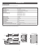
REPAIR PARTS CONTROL BOX 1 ITEM 1 2 3 4 5 PART NUMBER K74-36798-3 K94-36408-3 K94-36411 K75-36635 K1D8052-1CC 6 29-NP712 Battery 7 SOLPNL10W12V Solar Panel NOT SHOWN K74-36806-3 K94-36891 K77-36541 LA412CONTDC DESCRIPTION Standard Plastic Control Box Only Reset Switch with Product ID Piezo Alarm Control Board Bracket Control Board 4 2 Metal Control Box Only J15 Harness Antenna Standard Plastic Control Box (with control board) 6 3 5 7 GATE OPERATOR ARM 3 ITEM 1 4 2 1 5 46 PART NUMBER LA4
WIRING DIAGRAM STANDARD CONTROL BOX To LA412 protect against fire and electrocution: WIRING DIAGRAM • ECN: DISCONNECT power and battery BEFORE installing or servicing Reference: 06-37068 operator. 11/22/13 For continued protection against fire: • Replace ONLY with fuse of same type and rating.
WIRING DIAGRAM LARGE METAL CONTROL BOX To protect against fire and electrocution: • DISCONNECT power and battery BEFORE installing or servicing operator. For continued protection against fire: • Replace ONLY with fuse of same type and rating.
ACCESSORIES MISCELLANEOUS ENTRAPMENT PROTECTION DEVICES REMOTE ANTENNA EXTENSION KIT The remote antenna extension kit allows the antenna to be remotely installed. Model 86LM PHOTOELECTRIC SENSORS (MONITORED, NON-CONTACT) The photoelectric sensors are designed to detect an obstacle in the path of the electronic beam and stop the operator. Includes mounting brackets.
ACCESSORIES 33AH BATTERIES Upgrade 33 AMP-Hour Battery, 12 Vdc. Ideal for solar applications and extended battery backup. For use with Large Metal Control Box ONLY. Model A12330SGLPK BATTERY TRAY Required for 33AH applications. Model K10-36183) SOLAR BATTERY HARNESS Required for 33AH applications. Model K94-37236 BATTERIES Gate access system batteries replace or upgrade the gate operator batteries. Two identical 12 Vdc batteries are required for each gate operator.
1 2 3 4 5 6 7 TEMPLATE FOR POST BRACKET MOUNTING 7 6 5 4 3 845 Larch Avenue Elmhurst, Illinois 60126-1196 www.liftmaster.com 01-37071B © 2014, The Chamberlain Group, Inc.