
Owner manual

Area of Rescue Assistance system shall have push-button control circuits and indicator lights for Call
and Call Received functions. The Control Panel shall include power supply, status indicators, silence
and reset switches, and system test button. The components shall be mounted on a faceplate and
clearly marked for their respective uses. The faceplate shall be surrounded by an extruded alumi-
num frame with a hinge for attachment to a 4” deep enclosure. The assembly will swing open for
easy wiring and is key-locked closed to prevent tampering.
Features
General Description
109 Portwatch Way Wilmington, N.C. 28412 Phone: (800) 251-2512 Fax: (800) 251-9878
Internet: www.ledinc.com Email: sales@ledinc.com
Graphic Annunciators * Water Leak Detection
Fireman’s Smoke Control Panels * ARA Systems
Meets ADA requirements
Provides audible and visual
communication
Easy push-button operation
Secure key-locked enclosure
Plenty of room for wiring
Dependable solid-state circuits
Panel size - 9”w X 18”h X 4”d
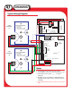
To place a call, the person needing assistance pushes the button on the call station. The LED on the
call station will flash to inform the user that the call has been sent. The control panel will indicate the
incoming call with an audible alarm and a flashing LED. The LED will identify the specific area
requesting help.
The operator pushes the acknowledge button to silence the audible. The call LED will go from flash-
ing to steady to inform the user that the request for help has been received. The LED will remain lit
until the control panel is reset. If additional calls are received, the new calls will resound the alarm
and the new request will be identified with a flashing LED. Intercom capability is not available on ST
systems.
System Operation
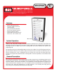
AREA OF RESCUE
ASSISTANCE PANEL
Model ST-8
ST
SERIES