
Manual
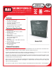

Non glare protective front
Low power consumption
Ultra Bright Light Emitting Diodes
Lamp Test - Standard
Per Point Diode Isolation on all inputs
Intended for indoor / dry location
1. Standby Voltage
Nominal 24 Vdc: Min. 18 Vdc to 36 Vdc
2. Standby Current
Typical Range 0 -15 ma
3. Alarm Current
Standby Current is increased Approx. 15
ma for each Activated LED
max input @ 3 Amps
4. Indicators
Super Bright LED’s - Red, Amber and Green
5. Activating Voltage
Positive or Negative as specified
6. Operating Temperature
32-100F (0-38C)
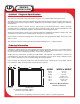
The Graphic Annunciator is housed in a sturdy Brushed Aluminum frame and attached to its backbox with a
vandal resistant “hidden” hinge. It is key-lockable to prevent unauthorized access.
Terminal strips (behind locked cover) facilitate the wiring of Field Devices. Screw connectors are complete with
captive wire protection and are automatically secured against loosening.
The electronic components are permanently installed on circuit boards. Electrical connections from the circuit
board(s) to the LED panel are made with Ribbon Connectors. Fire Alarm Panel driver modules can be
mounted inside of the annunciator panel.
Normal system operation is indicated by the lighted Green LED indicator. A lamp test switch is also provided.
When activated, ALL system indicators should light as a demonstration that all internal circuits, wiring and
LED’s are functioning properly.
The system is modular and can easily be changed or expanded. Must be installed with U.L. Listed equipment.
Features
Technical Specifications
General Description
109 Portwatch Way Wilmington, N.C. 28412 Phone: (800) 251-2512 Fax: (800) 251-9878
Internet: www.ledinc.com Email: sales@ledinc.com
Graphic Annunciators * Water Leak Detection
Fireman’s Smoke Control Panels * ARA Systems
LD
SERIES
Model LD-2
ANNUNCIATORS
GRAPHIC
S
T
A
T
E
O
F
C
A
L
I
F
O
R
N
I
A
S
T
A
T
E
F
I
R
E
M
A
R
S
H
A
L
BUILDINGS
NYC
MEA LIST ED