
Calculite Accessories/Option Instruction Sheet

I
/
.
.
INSTALLATION OF TRANSFORMER
lNSTFiUCTION SHEET NO
IS:7997
1285
READ AND UNDERSTAND THESE INSTRUCTIONS BEFORE INSTALLING
This transformer is intended for installation in accordance with the National Electrical Code and local or
federal code specifications. To prevent electrical shock, turn off electricity at fuse box before proceeding.
Retain these instructions for maintenance reference.
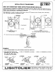
This transformer is used to supply a 120V fixture from a 277V branch circuit. Primary 277V; secondary
120V. 300 Watts maximum incandescent
load.
/G.R’w7i!i
120V. TO
FIXTURE
I
TRANSFORMER —
TRANSFORMER
— FIXTURE
FIG. 1
SUGGESTED LOCATION OF
TRANSFORMER
LINE IN
277V. - BLACK OR OTHER COLOR
FRAME-IN
1. Install TRANSFORMER
AS
“GREENFIELD ~
(Not Supplied)
f- 277V. SUPPLY
FIG. 2
MULTIPLE FIXTURES CONNECTION)
(Do not Exceed 300W Max. Rating of Transformer)
TRANSFORMER
FIG. 3
CIRCUIT DIAGRAM
using ADJUSTABLE MOUNTING BRACKET.
a. With MOUNTING BAR (order
b. With %“ CHANNEL (by others) c. With
separately) (18” - Cat. No. 1950;
27”- Cat. No. 1951), using
rectangular slots as shown.
11/2” CHANNEL (by others)
%“ CHANNEL
1% “
MO
(BY
(BY
A
MOUNTING
SCREWS &
SCREWS
SCREWS
BRACKET
FIG. 4
BRACKET
FIG. 5
1-1<51-1701 -[1:1?.o.,,,i,,.”,,,~ c...,.
@
SECAUCUS NEW JERSEY 0T094.0508
i