
Instruction Manual

Page 1 of 5
FL-4020 FLUORESCENT BALLAST CONTROLLER
Version 1.0 OWNERS MANUAL 10/06/2005
www.lightronics.com
Lightronics Inc 509 Central Drive Virginia Beach, VA 23454 Tel 757 486 3588
PRODUCT DESCRIPTION
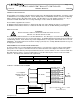
The FL-4020 is a four channel controller add on product for the AR-1202 Architectural dimmer. It provides control
of dimmable fluorescent lighting ballasts. The FL-4020 provides four 2400 Watt channels of fluorescent dimming
which is interfaced to the AR-1202 control circuitry. The AR-1202 uses its four auxillary channels (13 – 16 ) to
control the FL-4020. Dual SCR “zero crossing” switching is used to control the switched hot lines.
The FL-4020 is supplied in two versions:
FL-4020A: Controls ballasts which use a switched 120 VAC “hot” and a dimmed 120 VAC as a control signal.
FL-4020D: Controls ballasts which use a switched 120 VAC “hot” and a 0-10 VDC dimming control signal.
INSTALLATION
W
ARNING
MAKE CERTAIN POWER IS REMOVED FROM THE FEED CIRCUITS
BEFORE YOU BEGIN INSTALLATION.
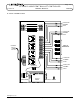
The unit should be wall mounted close to an AR-1202 dimmer. The unit may be "stood off" from the wall (aprox.
1") to assure clear airflow across the rear heat sink surface. A 120VAC 20 Amp power input must be provided for
each dimming channel. Each channel may control multiple ballasts as long as the channel load does not exceed
2400 Watts. The internal low current electronic circuitry is powered, via a 1/2 Amp 250VAC fast blow fuse, by the
H1 input power connection.
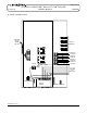
REQUIREMENTS FOR THREE PHASE OPERATION:
In order to provide zero crossing switching, the AR-1202 uses a specific phase sequence when operated with 3
phase power. The sequence convention must also be adhered to when connecting the FL-4020. The phase
connected to the AR-1202 H1 power input terminal must also be used for channels 1 and 4 of the FL-4020. The
AR-1202 H2 phase must be used for FL-4020 channel 2. The AR-1202 H3 phase must be used for FL-4020
channel 3. The table below summarizes this requirement.
POWER PHASE
A
R-1202 CHANNEL FL-4020 CHANNEL
H1 13 13
H2 14 14
H3 15 15
H1 16 16
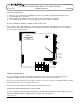
TYPICAL CONNECTION SCHEME
SWITCHED 120VAC
SWITCHED 120VAC
SWITCHED 120VAC
SWITCHED 120VAC
Control Signal
Control Signal
Control Signal
Control Signal
CH 13
CH 16
CH 15
CH 14
Channel 16 Control
Channel 15 Control
Channel 14 Control
Channel 13 Control
AR-1202
User supplied
120VAC feeds from
circuit breaker
p
anel
To
Lamp
Ballasts
FL-4020
Control Signal may be either 0 - 10 VDC
OR
120VAC Dimmed hot