Table of Contents System Overview ....................................................................................................................................................... 1 System Controls and Functions: Base Unit ............................................................................................................................................................... 2 Wireless Receivers ......................................................................................................
System Overview The DELTA X10 and X12 Wireless Sound Systems are powerful, rugged, and durable amplification systems designed for medium to large-sized groups both indoors and out. The systems contain inputs for up to two UHF wireless microphone receivers, optional integrated CD Player, two inputs for wired microphones, and an input for a line level audio source coming from a DVD player, TV/VCR, Computer, etc.
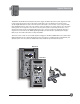
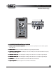
Controls and Functions System Base Unit 1 WIRELESS MIC 1 Delta X10 WIRELESS MIC 2 VOL VOL 7100R 7100R UHF TRUE DIVERSITY RECEIVER LightSPEED LightSPEED PWR Min A UHF TRUE DIVERSITY RECEIVER Max PWR Min B A CHANNEL Max B CHANNEL LOW BAT RF SCAN LOW BAT SQ RF SCAN SQ 2 Wireless Sound System WIRELESS MIC 1 WIRELESS MIC 2 VOL VOL 7100R 7100R UHF TRUE DIVERSITY RECEIVER LightSPEED UHF TRUE DIVERSITY RECEIVER LightSPEED PWR Min A Max PWR Min B A CHANNEL Max B CHANNE
Controls and Functions System Base Unit ...
VOL 7100R LightSPEED UHF TRUE DIVERSITY RECEIVER PWR Min A Controls and Functions Max B CHANNEL LOW BAT RF SCAN SQ Wireless Receiver(s) Delta X10 100-channel UHF Receiver Module 1 VOL 7100R Wireless Sound System WIRELESS MIC 1 LightSPEED WIRELESS MIC 2 VOL VOL 7100R 7100R UHF TRUE DIVERSITY RECEIVER LightSPEED UHF TRUE DIVERSITY RECEIVER LightSPEED PWR Min A UHF TRUE DIVERSITY RECEIVER Max PWR Min B A CHANNEL Max B PWR Min CHANNEL LOW BAT RF SCAN LOW BAT SQ RF SCA
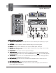
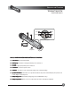
N O Controls and Functions Wireless Transmitter Handheld Microphone LOCK 1 2 DOWN 4 LOCK 6 SET 5 SET 6 HM-900 UP O N 7 End View of Microphone 3 CH: 002 LCD Display 8 Battery Compartment HM-900 HANDHELD MICROPHONE CONTROLS and FUNCTIONS 1. Power Switch: Turns the transmitter ON. 2. LCD Display: Information screen appears when the power is switched on. 3. Red LED: Lights up briefly when power is switched on. 4. Lock Button: Locks all microphone controls. 5.
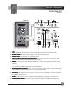
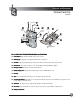
Controls and Functions Ligh Wireless Transmitter tSPE ED Belt-pack Red LED 3 Mute Switch 4 Mic Jack 1 On/Off Switch 5 6 8 Battery Charge Jack Gain Adjust 9 UP 10 7 2 Belt Clip LCD Display Set GT MT Door Latch 11 CH: 001 Ligh tSPE ED DOWN 9 12 Battery Compartment BP-900 BEL ACK TRANSMITTER CONTROLS and FUNCTIONS BELTT-P -PACK 1. Power Button: Turns the transmitter ON. (Hold for two seconds.) 2. LCD Display: Information screen appears when the power is switched on. 3.
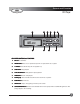
Controls and Functions CD Player 1 NO diSC 2 3 4 REPEAT A—B STOP 6 5 PLAY/PAUSE PROG EJECT — SKIP — SCAN/SEARCH 8 9 10 CD Player Front Panel 7 CD PLA YER CONTROLS and FUNCTIONS PLAYER 1. CD Slot: Insert CD here. 2. REPEA REPEATT Button: Press once to repeat a track, press twice to repeat an entire disc or playlist. 3. A - B Button: Sets start and end points for a playback loop. 4. STOP Button: Stops playback. 5. PLA Y/P AUSE Button: Starts playback or pauses playback.
System Installation Power/Charging 2 MASTER VOLUME BATTERY STATUS LIMIT min LOW OK max LEVEL LOW CUT LOW CUT music speech music speech WIRELESS MIC 1 WIRELESS MIC 2 EXTERNAL SPEAKER A SWITCHED 8 OHM EXTERNAL SPEAKER B LightSPEED MADE IN EUROPE 8 OHM CHARGING STATUS EXTERNAL POWER SOURCE 1 12VDC /4A 4 1 3 2 ON MUTE GND + 12V POWER ON OFF MUTE 3 DO NOT OPEN THE COVER. REFER SERVICING TO QUALIFIED PERSONNEL. REPLACE FUSE ONLY WITH THE SAME TYPE AND RATING.
System Installation Speaker Stand(tripod) 2 1 Safety Pin Locking Knob Locking Knob SPEAKER ST AND (TRIPOD) STAND 3 1. Extending the Legs: Loosen the lower knob and pull outward on two legs of the tripod. Extend the legs until the center post is just above the floor. The center post should NOT touch the floor. Tighten the lower knob. 2. Extending the Center Post: Loosen the upper knob and pull the center post up to the desired height. There are eight thru-holes in the center post.
System Installation Speaker/System Placement Typical stage placement for ONE Delta X system. Typical stage placement for TWO Delta X systems. SPEAKER PLACEMENT The Delta X system(s) should be placed in a location that is slightly in front of the area in which microphones will be used, typically at the front edge of a stage.
Operating Instructions System Base Unit TONE CONTROL 0 0 VOICE OVER MUSIC Delta X10 3 4 - 40 dB – 0 dB + LOW – HIGH + Wireless Sound System VOL 7100R UHF TRUE DIVERSITY RECEIVER LightSPEED Max PWR Min B A CHANNEL RF SCAN LOW BAT SQ REPEAT A—B RF SCAN SQ O U T PLAY/PAUSE PROG STOP CD-ROM ART GOES HERE NO diSC LINE/CD LEVEL VOICE OVER MUSIC min - 40 dB — SKIP — TONE CONTROL 0 0 I N O U T max – 0 dB LEVEL IN MIC 1 IN min max min max MASTER VOLUME SCAN/SEA
NO Operating Instructions Wireless Microphones Volume Delta X10 2 VOL 7100R UHF TRUE DIVERSITY RECEIVER LightSPEED Wireless Sound System WIRELESS MIC 1 A VOL 7100R Max PWR Min B A RF SCAN LOW BAT SQ REPEAT A—B Max CHANNEL Max B CHANNEL LOW BAT B UHF TRUE DIVERSITY RECEIVER LightSPEED PWR Min A PWR Min WIRELESS MIC 2 VOL 7100R UHF TRUE DIVERSITY RECEIVER LightSPEED CHANNEL RF SCAN SQ PLAY/PAUSE PROG STOP LOW BAT RF 4 1 SCAN SQ CD-ROM ART GOES HERE NO diSC EJ
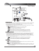
Operating Instructions Wired Microphone Delta X10 MIC 1 IN Wired Microphones [dynamic or condenser] LOW CUT Wireless Sound System WIRELESS MIC 1 WIRELESS MIC 2 VOL 7100R UHF TRUE DIVERSITY RECEIVER LightSPEED PWR Min A Flat Blade Screwdriver VOL 7100R UHF TRUE DIVERSITY RECEIVER LightSPEED Max PWR Min B A CHANNEL Max B CHANNEL LOW BAT RF SCAN LOW BAT SQ REPEAT A—B RF SCAN SQ music speech PLAY/PAUSE PROG STOP CD-ROM ART GOES HERE NO diSC — SKIP — LINE/CD LEVEL VOICE O
Operating Instructions CD Player Delta X10 Wireless Sound System WIRELESS MIC 1 WIRELESS MIC 2 VOL VOL 7100R 7100R UHF TRUE DIVERSITY RECEIVER LightSPEED A UHF TRUE DIVERSITY RECEIVER LightSPEED PWR Min Max PWR Min B A CHANNEL Max B CHANNEL LOW BAT RF SCAN LOW BAT SQ RF SCAN SQ REPEAT REPEAT A—B NO diSC LINE/CD LEVEL VOICE OVER MUSIC min - 40 dB — SKIP — O U T max – 0 dB LEVEL IN IN + LOW MIC 1 LIMIT LOW max HIGH + LOW CUT min BATTERY STATUS min – music
Operating Instructions Active Link Operation MUTE ON DO NOT OPEN THE COVER. REFER SERVICING TO QUALIFIED PERSONNEL. REPLACE FUSE ONLY WITH THE SAME TYPE AND RATING.
Operating Instructions Connecting External Speakers Delta X10 Output to any 8Ω speaker or speaker systems.
Operating Instructions External Audio IN/OUT Delta X10 Line/CD Level 2 Line IN 1 Wireless Sound System WIRELESS MIC 1 WIRELESS MIC 2 VOL VOL 7100R UHF TRUE DIVERSITY RECEIVER LightSPEED Max PWR Min B A Max SCAN LOW BAT SQ REPEAT A—B RF SCAN PLAY/PAUSE PROG STOP O U T CD-ROM ART GOES HERE NO diSC LINE/CD LEVEL VOICE OVER MUSIC min - 40 dB — SKIP — I N O U T max – 0 dB LEVEL IN SCAN/SEARCH IN + LOW min MIC 1 BATTERY STATUS LIMIT min LOW max HIGH IN + LOW CUT
VOL 7100R LightSPEED UHF TRUE DIVERSITY RECEIVER PWR Min A Operating Instructions Max B CHANNEL LOW BAT RF SCAN SQ Wireless Receiver(s) Frequency Group Volume 4 3 VOL 7100R Delta X10 LightSPEED UHF TRUE DIVERSITY RECEIVER PWR Min A Max B CHANNEL LOW BAT WIRELESS MIC 2 VOL VOL 7100R 7100R UHF TRUE DIVERSITY RECEIVER LightSPEED PWR Min A UHF TRUE DIVERSITY RECEIVER LightSPEED Max PWR Min B A CHANNEL SCAN SQ 5 Manual Channel Select Buttons Wireless Sound System WIREL
VOL 7100R LightSPEED UHF TRUE DIVERSITY RECEIVER PWR Min A Max B CHANNEL LOW BAT RF SCAN Operating Instructions SQ Wireless Receiver(s) MANUAL CHANNEL SELECTION: 6. Left Channel Button: Pressing the Left Channel button changes the first number (0-9). 100-channel UHF Receiver Module 7. Right Channel Button: Pressing the Right Channel button changes the second number (0-9).
N O Operating Instructions Wireless Transmitter Handheld Microphone Channel Selection – Handheld TTransmitter ransmitter Once a channel has been selected on the receiver, you now need to select that same channel on the handheld transmitter. If you have a belt-pack transmitter, go to page 23 for channel selection instructions. •Turn the microphone on by sliding the switch on the barrel to the ON position. The red LED will flash once.
N O Operating Instructions Wireless Transmitter Handheld Microphone Sensitivity Level This function allows the user to set the gain structure of the microphone to best fit the voice level of the person speaking into it. A person with a very loud, booming voice may want the microphone set to a sensitivity level of 1 or 2. A person with a very soft voice will be better off with the microphone set to a sensitivity of 3 or 4.
N O Operating Instructions Wireless Transmitter Handheld Microphone REPLACING THE BA TTERIES BATTERIES 1. To replace the batteries, unscrew the end cap to reveal the battery compartment. 2. Remove or replace the batteries as shown. The microphone requires two AA sized batteries stacked end to end. 3. Note the polarity in the battery compartment. Typical battery life is about 8 hours.
Operating Instructions Wireless Transmitter Ligh tSPE ED Belt-pack Channel Selection – Belt-pack TTransmitter ransmitter Once a channel has been selected on the receiver, you now need to select that same channel on the belt pack transmitter. NOTE: Transmitters and receivers are available in 5 different frequency groups. Verify that the letter code that blinks on the receiver (when powered ON) matches the letter code on the frequency sticker in the battery compartment of the transmitter.
Operating Instructions Wireless Transmitter Ligh tSPE ED Belt-pack CH: 001 720.250M 2 Gain Adjust 1 GT MT GT MT Alkaline CH: 001 4 Ligh 3tSPEED NiMH Nickel Metal Hydride Rechargable 1. Transmitter Mute: The MUTE switch turns the transmitter’s audio signal on or off. The audio is off when the red LED is flashing. 2. Gain Adjust: When changing microphones or users, it may be necessary to adjust the transmitter gain based on differing microphone sensitivities and voice levels.
Operating Instructions Wireless Transmitter Ligh tSPE ED Belt-pack Charging the Batteries (NiMH Rechargeable Batteries ONL Y): ONLY): Make sure there are NiMH Rechargeable Batteries in the transmitter before plugging in the charger. WARNING: Do not attempt to charge alkaline batteries. They can overheat and expand, creating a significant hazard and damaging the transmitter. (This is not covered by warranty.) •Switch the transmitter power off.
Operating Instructions CD Player REPEAT NO diSC Playing a Compact Disc When a CD is not loaded in the CD player, the LCD screen will display the text ‘no disc’. A—B EJECT STOP — SKIP — PLAY/PAUSE PROG SCAN/SEARCH To stop playback, press the PLAY/PAUSE button once again or press the STOP button. When paused, the PAUSE symbol appears on the display. 1 NO diSC 01 00:12 To play a disc, gently insert it into the CD slot. The CD player will ‘grab’ the CD and load it automatically.
Operating Instructions CD Player ... continued To create a loop, press the A->B button during playback at the time index you have chosen as the beginning of the loop. REPEAT 2 3 4 PROGRAM 5 6 7 8 9 10 11 12 01 P :02 A---> 01 00:32 13 14 15 Press the A->B button again when the time index reaches the chosen end point of the loop. REPEAT A---> B 01 00:23 To save the selection, press the PROG button again. The track number will appear in the grid.
Trouble Shooting Guide No sound when using any input (CD player player,, Line In, Wired Microphones, Wireless Microphones): 1. DELTA X main power should be turned ON. The green ON LED should be lit. If it does not light when the system is switched on, the battery is most likely too weak and needs to be plugged into the charger. 2. Make sure the main power switch is set to ON and not MUTE. 3. Check the setting of the MASTER VOLUME control. This control sets the amount of audio coming out of the speakers.
System Specifications Delta X10/12 Base Unit DELTA X10 DELTA X12 Nominal SPL (1W/1M) ......................................... 97 dB .................................................................................. 100 dB Maximum SPL ...................................................... 116 dB ................................................................................ 120 dB System Power (RMS) .......................................... 50 W at 8 W ....................................................
Channel/Frequency Assignments Wireless Channel Assignments LightSPEED Channel Frequency Range E ...................................................... 620.000 – 644.750 H ..................................................... 645.000 – 669.750 L ...................................................... 670.000 – 694.750 P ...................................................... 695.000 – 719.750 U ..................................................... 720.000 – 744.
Warranty The LightSPEED Technologies Delta X10 and Delta X12 are warranted to be free from defects in materials and workmanship for the period of SIX (6) YEARS from the date of original purchase, subject to the following conditions: 1. The product must have been purchased from LightSPEED, an authorized LightSPEED Technologies Dealer, or LightSPEED representative. 2. LightSPEED Technologies must perform all warranty service.
User Notes LightSPEED Technologies • Wireless Sound Solutions • Toll Free: 1-800-840-3662 32