TM User Manual 2 February 2001
Lightwave Communications, Inc. 100 Washington Street Milford, CT 06460 USA (800) 871-9838 • (203) 878-9838 • Fax: (203) 874-0157 Email: info@lightwavecom.com • Internet: www.lightwavecom.com LCI Asia/Pacific Postal address: P.O. Box 19 Glen Iris VIC 3146 Australia Delivery address: 16 Network Drive Port Melbourne VIC 3207 Australia +61 3 9646 1144 • Fax: +61 3 9645 3377 Email: sales@lightwavecom.com.au • Internet: www.lightwavecom.com.
1.0 Product Description............................................................................................................. 1 1.1 Video............................................................................................................................... 1 1.2 Keyboard/Mouse............................................................................................................. 1 1.3 Features................................................................................................
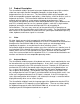
1.0 Product Description The ServerSwitch 8200 is designed to transport keyboard/mouse and high-resolution video from up to eight Sun® or compatible computers to video displays and keyboard/mouse sets for two users. The ServerSwitch 8200 is plug-compatible with Sun® and compatible computer workstations, video displays, and user devices (such as keyboards and mice). The ServerSwitch 8200 can be used to create a variety of networks with no impact on system processing power or performance.
1.3 Features The ServerSwitch 8200 features: § rack-mountable chassis § control up to eight Sun® or compatible workstations with one ServerSwitch § control up to 80 Sun® or compatible workstations using 10 cascaded ServerSwitches § two user ports allow simultaneous use of the ServerSwitch from two separate stations § attached CPUs only require one keyboard, mouse, and monitor per user for control 1.4 Physical Description The ServerSwitch 8200 chassis measures 17.5 inches (44.45 cm) wide by 3.5 inches (8.
2.0 Installing the ServerSwitch 8200 2.1 Location and Operational Safety The ServerSwitch 8200 may be mounted in a rack, or may be used as a desktop unit. If used as a desktop unit, the rack mount "ears" may be removed, and rubber feet (supplied with the ServerSwitch 8200) should be attached. If mounting the unit in a rack, ensure that there are screws in each of the mounting holes and that the "ears" are firmly seated against the rack once the screws are tightened.
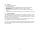
Male 8 pin mini-DIN Male 13W3 See Appendix A for cable technical specifications and Lightwave Communications part numbers. 2.3 Connecting Sun® Servers If the server has a 13W3 or HD15 video connector, a Sun® compatible video cable with two male ends may be used. See Appendix A for cable specifications and part numbers.
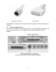
Connectors on a Sun® CPU with HD15 video output CPU connectors on the ServerSwitch 8200 Connecting Sun® servers to the ServerSwitch 8200 is very simple. First, be sure that power is off to all CPUs that will be connected to the ServerSwitch 8200. A video cable should be connected to the video output of the Sun® server that will be connected to the ServerSwitch.
CPU connections to the ServerSwitch 8200 using 13W3 and HD15 video cables Lightwave Communications recommends using cables less than 75 feet in length to connect Sun® servers to the ServerSwitch 8200. Lengths over 75 feet cause significant signal degradation. If the ServerSwitch 8200 and attached server must be more than 75 feet apart, use Lightwave Communications’ VDE/200 to extend the useful range of the video signal. 2.
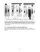
User A properly paired User B properly paired Before starting, be sure that power is off to the ServerSwitch 8200 and the users' monitors. The users' monitors are attached to the two 13W3 connectors marked "USER" on the rear of the ServerSwitch 8200. The keyboard/mouse sets are attached to the two 8 pin mini-DIN connectors marked "USER". Be sure that the monitor and keyboard/mouse set for each user are properly paired to the user output ports (i.e.
2.5 Connecting Multiple ServerSwitches In each cascade, there is a master unit, and one or more auxiliary units. The users are directly attached to the master unit, and can control and access all the auxiliary units through that master unit. There may be up to 9 auxiliary units in a cascade along with one master unit, allowing the two users to control 80 CPUs. To connect several ServerSwitches in a cascade, first select the unit that will be the master unit.
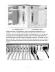
Cable connections to a cascade auxiliary unit Cable connections to the end cascade auxiliary unit 9
Attach two 13W3 video cables to the two user video ports on the back of the last auxiliary unit in the cascade, and secure them to the ports using the screws on the cable connector. Attach the other ends of the cables to the CASCADE IN video ports on the next auxiliary unit closer to the master unit (the next unit upstream). Be sure that the USER A port is attached to the CASCADE IN A port, and the USER B port is attached to the CASCADE IN B port.
End auxiliary unit with cables Note that there are no keyboard/mouse lines connected between cascaded units. Keyboard and mouse signals are transported over the serial cables attached to the CONTROL ports. Once all units are attached in the cascade, turn on power to the users' monitors, and then power up the master unit. Once the master unit has completed its power-on diagnostic, power up the auxiliary units in succession down the cascade.
3.0 Operating the ServerSwitch 8200 The ServerSwitch 8200 is designed to allow two users to access and control up to 80 Sun® or compatible servers. The users may select the servers either from the frontpanel buttons or an on-screen menu. The individual CPU ports may have names associated with them to allow for more intuitive access of the attached CPUs. 3.1 The On-Screen Menu The on-screen menu is accessed by pressing Control and Alt Graph simultaneously.
3.3 Selecting a Server Port The users have two means to select a server port: the front panel buttons and the onscreen menu. The front panel buttons will increment or decrement the server port number for the selected user. If a port has been selected by the other user on the ServerSwitch, then it will not appear as the user scrolls through the server ports using the front panel buttons.
only those server ports available on the master unit are shown on the first screen (other ports are shown by selecting Next unit at the bottom of the menu). Pressing J or selecting Jump to port… from the menu allows a user to directly select a server port. The ServerSwitch will prompt the user for a server port by changing Jump to port… to Enter port: on the on-screen menu.
3.3.2 Auto Scan The ServerSwitch can automatically scan through each attached server in auto scan mode. Servers may be individually selected for inclusion in the auto scan; all server ports are selected by default. See section 3.5.3 for more information on selecting server ports for auto scan. A user may begin auto scan by pressing A at the on-screen menu to change no Auto scan to start Auto scan. scan Once the user exits from the on-screen menu by pressing , the auto scan will begin.
software version is listed at the top of the System Setup menu. See Appendix B, Setting Factory Defaults and Flash Upgrade Procedure for more information. Settings in the System Setup menu are automatically saved each time the user exits from the menu. 3.4.
3.4.3 Error Message Duration This option determines the amount of time each error message will appear on the front panel LCD display. Users may change this value either by pressing the highlighted character (M M) or moving the highlight bar to the option and using the + or - keys to change the value. Pressing the highlighted character will increment the time until it reaches the highest value, and then start again at the lowest value. Using the + and keys allows users to increment or decrement the value.
3.5 Port Setup Port Setup Edit Port Names +Port 1 +Port 2 +Port 3 +Port 4 +Port 5 +Port 6 +Port 7 +Port 8 F8 toggles Inactive msg +/keypad + or – toggles autoscan Enter to edit port name : Port Autoscan Enabled Esc exits Port Setup Menu In addition to changing server port names, users may also configure other parameters from the Port Port Setup menu. Users may enable or disable auto scan for each port, and may prevent the front panel LCD display from showing error messages for inactive server ports. 3.5.
The Port Setup menu allows users to change several options for each port. To change the server port name, use the up and down arrow keys to move the highlight bar to the desired server port, and press to select that server port for change. The user may enter the new server port name once the highlight bar changes to show only the server port name.
3.6 Menu Window Setup Menu Window Setup move move move move Up Down Left Right Background color Foreground color Highlight color Select menu color Esc exits Menu Window Setup Menu Users may alter the appearance of the menu windows by selecting this option. The colors and position of the menu can be altered to suit the users' preferences. Each user's preferences are stored separately, so each user may specify a different appearance for their individual menus.
3.7 Server Window Setup Users may alter the appearance and position of the window that displays the server port name on-screen when a server port is selected. When Server window setup… is selected from the System setup menu, the large menu disappears and a small window that is the same size and shape as the server name window will appear with the move Up option in it. Only one option at a time will appear in the window.
Appendix A Cable Specifications This appendix outlines the required cable specifications for the ServerSwitch 8200. Additionally, part numbers for cables available from Lightwave Communications are provided. Serial Cables: A serial data cable is provided with each ServerSwitch 8200. This cable may be used either to connect the unit in a cascade or to update the software in flash memory.
HD15 Video Cable, MM 2M (6’) HD15 Video Cable, MM 3M (10’) HD15 Video Cable, MM 4.5M (15’) HD15 Video Cable, MM 7.6M (25’) HD15 Video Cable, MM 15M (50’) HD15 Video Cable, MF (extension) 2M (6’) HD15 Video Cable, MF (extension) 3M (10’) HD15 Video Cable, MF (extension) 7.6M (25’) HD15 Video Cable, MF (extension) 15M (50’) HD15 Video Cable, MF (extension) 23.3M (75’) Sun Keyboard Cable, 8 pin Mini-DIN, MM, 2M (6.6') Sun Keyboard Cable, 8 pin Mini-DIN, MM, 3M (9.8') Sun Keyboard Cable, 8 pin Mini-DIN, MM, 4.
Appendix B Setting Factory Defaults and Flash Update Procedure B.1 Setting Factory Defaults If it becomes necessary to reset the ServerSwitch 8200, the users may do so from the System Setup menu. Once at the System Setup Setup menu, access the defaults/flash update menu by pressing the key. Press and hold the key, and then press the Y key to confirm that the ServerSwitch parameters and server port names should be set to the factory default values.
1. Connect the laptop serial port to the CONTROL IN port of the ServerSwitch 8200. Start the communications software, and configure the communications parameters to 38,400 baud, 8 data bits, no parity, 1 stop bit, and DTE (38.4K 8N1 DTE). Select the correct serial port (i.e., COM1) as the I/O port if not already selected. 2. From a ServerSwitch 8200 user port (either A or B will work), access the main on-screen menu by pressing and simultaneously.
Appendix C Identification of Exterior Components Front: Rear: First Chassis Revision 26
Second Chassis Revision Third Chassis Revision Key to Rear View: 1. 2. 2A. 3. 4. 4A. 5. 6. 6A.
7. 8. 9. 10. 11. 12. 13.
Appendix D D.1 System Specifications Physical Width: Depth: Height: 17.5 inches (44.45 cm) 8.0 inches (20.32 cm) 3.5 inches (8.89 cm) 1 RU Shipping weight: 15 lbs. (6.8 kg) D.2 Environmental Operating temperature range: Operating humidity range: 32°F – 122°F (0°C – 50°C) 10% – 90% RH, non-condensing Storage temperature range: Storage humidity range: 14°F – 158°F (-10°C – 70°C) 10% – 90% RH, non-condensing Heat generated in normal operation: 102.4 BTU/hr D.
Keyboard/Mouse connector: Keyboard/Mouse signal format: 8-pin mini-DIN female Sun keyboard/mouse D.4.3 Cascade Ports Cascade In video connector: 13W3 female Control In connector: Control Out connector: DB9 female DB9 male Control signal format: RS-232 serial and Sun keyboard/mouse signal, proprietary pinout D.