Zaubzerstrasse 11 - 81677 Munich - Germany Tel: +49 (0)89 306381-0 - Fax: +49 (0)89 306381-20 www.lightwave.
WARRANTY INFORMATION The warranty period on this product (parts and labor) is one (1) year from the date of purchase. Please contact Lightwave Communications at +49 (0)89 306381-0 or office@lightwave.de for information regarding repairs and/or returns. A return authorization number is required for all repairs/returns. COPYRIGHT Copyright © 2003 by Lightwave Communications. All rights reserved.
TABLE OF CONTENTS INTRODUCTION............................................................................................................................................................. 1 Available Options......................................................................................................................................................... 1 Types of User Input Devices Supported................................................................................................................
TABLE OF FIGURES Figure 1- Connect a VGA multi-scan monitor ................................................................................................................. 4 Figure 2- Connect the device(s) ...................................................................................................................................... 4 Figure 3- Connect the AC adapter ..................................................................................................................................
INTRODUCTION INTRODUCTION The Lightwave Communication USB-Wizard USB KVM switch allows access to any Windows, MAC, or SUN USB CPUs from one monitor, USB keyboard and USB mouse (up to 8 CPUs as a single switch or 64 CPUs when cascaded). Internal microprocessor circuitry allows all USB CPUs to be booted simultaneously without keyboard error. Port selection is accomplished by front panel push buttons or commands typed on the keyboard. Port lights & status LEDs continuously update on the front panel.
DEFINITIONS DEFINITIONS • • USB Composite Device USB Hub • CPU • • Input Device System A USB device that contains multiple endpoints each representing input devices that cannot be separated (i.e. a keyboard with a built-in mouse) A USB device that allows one or more USB input devices to plug in to the USB. The hub has exactly one upstream port with one or more downstream ports which input devices connect to Enclosure that contains the operating system and processor (i.e.
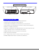
F E A T U R E S A N D F U N C T IO N S Rear View of USB Wizard Front View of USB Wizard 8 7 2 1 R V D O V I D E O C P U 9 8 C P U 7 V I D C P U 6 D E O 6 V I D E O 7 8 5 V D C 2 A V I E 5 C P U 5 V I C P U 4 3 C P U 3 D E O O 2 C P U 2 M V I D E O 4 V I D E O N O 1 C P U 1 M O D E O I E T I R D E V IC E S D A IS Y D A IS Y IN O U T 3 1 - C O M M A N D S C A N 2 4 3 5 6 7 8 O N 1 2 3 4 5 6 + 1 0 1 1 6 4 5 FEATURES AND FUNCTIONS F
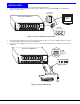
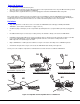
INSTALLATION INSTALLATION 1. 2. It is not necessary to turn the CPUs or monitors OFF during this installation. Connect the cable from a VGA multi-scan monitor to the 15HD connector labeled “MONITOR” on the USB Wizard switch. (See Fig. 1 below.
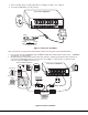
5. 6. When cascading switches, configure dip-switches accordingly (see Tables 1 & 2 on page 8). Power-up the USB Wizard. (See Fig. 3 below.
Power-Up Sequence • • • The USB Wizard can be powered at any time. The CPUs can be powered at any time although if a CPU needs a keyboard and/or mouse at power-ON it should be powered after connecting to and powering-ON the USB Wizard. USB input devices (keyboard and mouse) can be hot plugged to and from the USB Wizard switch at any time.
CASCADING CASCADING The USB Wizard can be cascaded as shown in Fig. 6 below. If USB Wizard switches are being cascaded, configure the dip-switches accordingly (see Tables 1 and 2 on page 8). Configuration All units are configured using the 6-position dip switch (located on the front of each unit) according to the tables on page 8 (1 & 2). Cascaded Installation a. b. c. Configure each dip switch as per the tables on page 8 before proceeding.
Front Panel Configuration Switches Table 1 * (default settings) Switch STAND-ALONE SWITCH SLAVE MASTER W/4-PORT SLAVES MASTER W/8-PORT SLAVES MASTER W/16-PORT SLAVES SW1 OFF* ON OFF OFF OFF SW5 OFF* OFF OFF ON ON SW6 OFF* OFF ON OFF ON Table 2 * (default settings) Master & Slave dip switch 2-4 Settings SW2 SW3 SW4 Master withSlave Setting OFF* OFF* No Slave Attached N/A OFF* OFF OFF OFF 1 Slave attached Slave #1 OFF OFF OFF ON ON ON ON OFF ON ON OFF OFF ON ON ON OFF ON OFF ON OFF ON 2 Slaves attached
USINGTHE THE USB WIZARD KVM SWITCH USING Once the USB Wizard switch is properly connected, the USB Wizard will enable a connection to be made between the CPUs attached to its VIDEO and CPU ports and the monitor and input devices attached to the MONITOR and DEVICES ports. The LEDs on the control panel of the USB Wizard will illuminate depending on which port (and corresponding CPU) is being connected to the monitor and input devices.
OSD CONTROL OSD superimposes a menu system on the user’s video screen with a list of all connected CPUs. OSD allows CPUs to be named (with up to 12-character names). OSD then allows selection of CPUs by that name. Connected CPUs can be listed by name or by port number. OSD Search Mode enables the user to type in the first few characters of the CPU's name and the OSD will locate it. Help screens assist with all OSD functions.
User Login Mode User login mode requires a user to login with a user name and password from the list created by the administrator. This mode will also disable use of the front panel until the user logs in. Function: Adds a character to the user name/password Keystroke: A-Z 0-9 Removes previous character from the user name/password Submit user name/password Exit USER LOGIN and return to previous mode. This function is only available if security is not currently active.
Administrator Password To change the administrator password press from the Administration Mode menu. The administrator is able to change the administrator password as needed (see Fig. 11). Two edit fields are available, one for password, the other for verify password. The password can be up to 13 characters in length. Note: The default password for the administrator is ADMINISTRATOR.
System Access List To enter the System Access List press + from the User Name List menu. The System Access List displays a list of numbers representing the ports so the administrator can change access rights to the ports for the selected user. The user’s name is displayed at the top of the access list. The mouse is used to change access rights by clicking on a given number to toggle a port’s status.
OSD Command Mode (Cont'd) Function: Keystroke: Enter Maintenance Mode Ctrl + M Sets scan time-out on each port Ctrl + T - (0-2) x - (0-9) x - Selects a specific port Ctrl + P - (0-9) x - (0-9) x (Pxx would be P01, P02, etc.) Enters Search Mode and adds a character to search string and selects the CPU’s name that matches best.
Scan Mode To activate Scan Mode press + from the Command Mode menu. When in Scan Mode the switch scans to each port with a CPU powered-ON. (The SCAN LED on the front panel will illuminate and remain ON while in Scan Mode. ) The port with the CPU powered-ON remains active while in use until it becomes idle for the configured dwell time (default time-out period is 5 seconds) before switching to the next powered-ON CPU port. See Command Mode section above for configuring the scan dwell time.
Search Mode To enter Search Mode, type any alphabetical or numeric character when the Command Mode menu is on the monitor. Search Mode enables the user to enter and maneuver through a list of CPU names. The CPU name best matching the characters typed is selected. The list of CPUs may also be searched for a specific (or similar) name. The following commands are valid when the search option has been invoked from Command Mode.
Maintenance Mode (Cont'd) Function: Keystroke: Move OSD menu to the left Make OSD menu taller T Make OSD menu shorter S Change user password. (Present only when a standard user is logged in.) P Log current user out and return to User Login Mode. Q Activate security features. Present only when security is available but not active. A Enter Administration Mode. Option present only when Administrator is logged in.
KEYBOARDFEATURES FEATURES KEYBOARD The keyboard configuration of each CPU is saved in the USB Wizard. For example, if the CPU attached to Port 2 had CAPS LOCK and NUM LOCK selected the last time that CPU was accessed, then they will automatically be set when that CPU is accessed again. Keyboard-To-Computer Translation (See Fig. 19 on page 19 for reference.) The USB Wizard enables a mixture of otherwise incompatible peripheral computer components to be connected together.
E s c ~ N u m L o c k B a c k s p a c e ` T a b E n te r C a p s L o c k S h ift S h ift E n te r C trl A lt A lt C trl T y p ic a l 1 0 1 K e y b o a r d E s c F 1 F 2 F 3 F 4 F 5 F 6 F 7 F 8 F 9 F 1 0 F 1 1 ~ P r in t S c re e n S y s R q F 1 2 S c r o ll L o c k P a u s e B re a k N u m L o c k B a c k s p a c e ` T a b E n te r C a p s L o c k S h ift S h ift E n te r C trl A lt A lt C trl A p p lic a tio n K e y W in d o w s L o g o K e y W in d o w s L o g o K
HOWTO TODISABLE DISABLEOPERATING OPERATINGMODES MODES HOW Two operating modes of the USB Wizard can be disabled if desired. The Command Mode can be disabled which would also disable the Scan Mode, or, the Scan Mode can be separately disabled leaving Command Mode enabled. To disable these operating modes, the user must get access to the jumpers block. This block is located close to the dip switches on the circuit board the keyboards plug into (called the digital board) inside the USB Wizard. (See Fig.
5. Grasp firmly the front panel and slide the front panel up out of the slots in the plastic case that support it. Once the panel is clear of the case, pivot the panel back approximately 1", just enough to expose the jumper block. (See Fig. 22.) Be careful not to dislodge the connection of the ribbon connecting the LED board to the digital board. If it appears to become loose, be sure to reseat the connection before re-assembly. Now follow the instructions under "CONFIGURING THE JUMPER BLOCK" below.
TROUBLESHOOTING TROUBLESHOOTING PROBLEM: SOLUTION: Keyboard Errors Check cable connections on each CPU and the switch. PROBLEM: SOLUTION: No Video Check cable connections on each CPU and the switch. Verify that keyboard and video connect from each CPU to matching ports. After reconnecting, CPU may need to be re-booted in order to sense the monitor connection. PROBLEM: SOLUTION: No Mouse Movement Check cable connections of mouse. Verify that mouse driver was loaded. SERIAL NO.