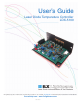
User’s Guide Laser Diode Temperature Controller LDX-5100 ILX Lightwave Corporation · P. O. Box 6310 · Bozeman, MT, U.S.A. 59771 · U.S. & Canada: 1-800-459-9459 · International Inquiries: 406-556-2481 · Fax 406-586-9405 ilx.custhelp.com · www.ilxlightwave.
TA B L E O F C O N T E N T S TABLE OF CONTENTS Table of Contents . . . . . . . . . . . . . . . . . . . . . . . . . . . . . . . . . . . . . . . . . . . i Safety and Warranty Information . . . . . . . . . . . . . . . . . . . . . . . . . . . . . . iii Safety Information and the Manual . . . . . . . . . . . . . . . . . . . . . . . . . . . . . . . . . iii General Safety Considerations . . . . . . . . . . . . . . . . . . . . . . . . . . . . . . . . . . . . iii Safety Symbols . . . . . . . . . . . . . . . . . .
TA B L E O F C O N T E N T S TEC Gain . . . . . . . . . . . . . . . . . . . . . . . . . . . . . . . . . . . . . . . . . . . . . . . . . . . . . . . 6 Measurement/Control (J2) . . . . . . . . . . . . . . . . . . . . . . . . . . . . . . . . . . . . . . . . . 6 Output Off . . . . . . . . . . . . . . . . . . . . . . . . . . . . . . . . . . . . . . . . . . . . . . . . . . . . 6 Output Monitors . . . . . . . . . . . . . . . . . . . . . . . . . . . . . . . . . . . . . . . . . . . . . . . 7 Thermistor Monitor . .
SAFETY AND WARRANTY INFORMATION The Safety and Warranty Information section provides details about cautionary symbols used in the manual, safety markings used on the instrument, and information about the Warranty including Customer Service contact information.
S A F E T Y A N D WA R R A N T Y I N F O R M A T I O N Safety Symbols S AFETY S YMBOLS This section describes the safety symbols and classifications. Technical specifications including electrical ratings and weight are included within the manual. See the Table of Contents to locate the specifications and other product information.
S A F E T Y A N D WA R R A N T Y I N F O R M A T I O N Warranty WARRANTY ILX LIGHTWAVE CORPORATION warrants this instrument to be free from defects in material and workmanship for a period of one year from date of shipment. During the warranty period, ILX will repair or replace the unit, at our option, without charge. Limitations This warranty does not apply to fuses, lamps, defects caused by abuse, modifications, or to use of the product for which it was not intended.
S A F E T Y A N D WA R R A N T Y I N F O R M A T I O N Warranty Claims for Shipping Damage When you receive the instrument, inspect it immediately for any damage or shortages on the packing list. If the instrument is damaged, file a claim with the carrier. The factory will supply you with a quotation for estimated costs of repair. You must negotiate and settle with the carrier for the amount of damage.
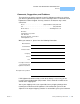
S A F E T Y A N D WA R R A N T Y I N F O R M A T I O N Warranty Comments, Suggestions, and Problems To ensure that you get the most out of your ILX Lightwave product, we ask that you direct any product operation or service related questions or comments to ILX Lightwave Customer Support. You may contact us in whatever way is most convenient: Phone . . . . . . . . . . . . . . . . . . . . . . . . . . . (800) 459-9459 or (406) 586-1244 Fax . . . . . . . . . . . . . . . . . . . . . . . . . . . . . . . . . . . .
S A F E T Y A N D WA R R A N T Y I N F O R M A T I O N Warranty in a container with at least 3 inches (7.5 cm) of compressible packaging material on all sides.
CHAPTER 1 INTRODUCTION This manual contains operation, calibration and specification information for the LDT-5100. It is recommended that the user become thoroughly familiar with this information prior to operating the LDT-5100. If any of the following symptoms exist, or are even suspected, remove the LDT-5100 Temperature Controller from service. Do not use until trained service personnel can verify safe operation.
CHAPTER 1 INTRODUCTION Product Overview Product Overview The LDT-5100 Temperature Controller is a device which, when powered by the appropriate supply, measures the temperature dependent resistance of a thermistor. Using this resistance as feedback, it stabilizes temperature by driving current to a thermoelectric (TE) module. The TE drive for the LDT-5100 is bipolar (positive current to cool; negative current to heat). This allows for highly stable temperatures and fast settling times.
INTRODUCTION Specifications1 CHAPTER 1 Specifications 1 INPUTS Power Supply + 12 to 18 Volts at 75 mA2 + 4.
CHAPTER 1 INTRODUCTION Specifications1 LED Indicators 4 LDT-5100 Output On PCB pads for external LED (10 mA) and open collector output6 TEC Open Error PCB pads for external LED (10 mA) and open collector output6 Sensor Open Error PCB pads for external LED (10 mA) and open collector output6 GENERAL LDT-5100 Size 1.75” x 3.75” x 5.5” (44mm x 95mm x 139mm) Weight 8.75 oz Operating Temperature 0 to 50 oC Storage Temperature -40 to 70 oC 1. 2. 3. 4.
CHAPTER 2 OPERATION See Figure 2.1 for location and identification of control connectors and jumpers. Thermistor Resistance Set Point Two methods of thermistor R set point control are provided in the LDT-5100; internal resistor or external resistor. A jumper, “RESISTOR SEL”, (J6) is used to select which resistor is used as the set point reference for the control loop. (A jumper on the left and center pins selects external resistor. Right and center pins select internal resistor).
CHAPTER 2 OPERATION Figure 2.
OPERATION Thermistor Current Source CHAPTER 2 Thermistor Current Source For a greater range of temperature sensing, two current sources are provided on the LDT-5100; 100 µA and 10 µA. Each source is selectable on the “THERMISTOR CURRENT” jumper (J5). The default setting from the factory is 100µA. Note: If the jumper is removed, the 100 µA current source (default) is selected. The choice of current source will depend on the thermistor sensor used.
CHAPTER 2 OPERATION Measurement/Control (J2) Output Monitors The LDT-5100 has two buffered output monitors present on the measurement / control connector (J2). These monitor the actual thermistor resistance and ITE (TE drive current). Thermistor Monitor The thermistor monitor (pin 10) provides an output voltage which is proportional to the thermistor sense resistor value.
OPERATION LED Indicators CHAPTER 2 supply voltage, this threshold is not a fixed value. Under normal operation (with a low impedance TE), the control line will be in a high impedance state. Output On/Off (pin 2) This control line indicates if the TE output is on (driving current to a TE load). A ground at this control line indicates that the output is off and no current is being driven through the TE modules.
CHAPTER 10 LDT-5100 2 OPERATION DC Power-In Connector (J3)
CHAPTER 3 CALIBRATION Thermistor Current Source Calibration To calibrate the thermistor current source, connect an ammeter in series with a 10 kΩ resistor at the output connector (J1). 1 Place the thermistor current jumper (J5) in the 100 µA position. 2 Adjust trim pot R51 to read 100.00 µA on the current meter. 3 Place the thermistor current jumper (J5) in the 10 µA position. 4 Adjust trim pot R50 to read 10.00 µA on the current meter.
CHAPTER 10 LDT-5100 3 CALIBRATION TE Current Limit Calibration