
User's Manual

OPERATION
LED Indicators
05_07 LDT-5100 9
CHAPTER 2
supply voltage, this threshold is not a fixed value. Under normal operation (with a
low impedance TE), the control line will be in a high impedance state.
Output On/Off (pin 2)
This control line indicates if the TE output is on (driving current to a TE load). A
ground at this control line indicates that the output is off and no current is being
driven through the TE modules.
LED Indicators
Pads are located on the LDT-5100 PCB to allow direct connection of indicator
LEDs. The indicator LEDs correspond to the three status lines described above.
These pads are internally referenced and do not require an external supply
connection. The ANODE pin of all three LEDs are connected so that a single
common wire can be used for remote LED indicators. The error LED indicators
(TEC Open (D3) and Thermistor Open (D1) are illuminated when an error is
sensed. The OUTPUT ON indicator (D4) is illuminated when the output is on.
Note: If LEDs are used, the current requirement for the -15V supply should be increased
accordingly.
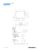
TEC I/O Connector (J1)
The 15-pin D-sub I/O connector pinout is shown in Figure 2.1. Simply connect
your TE module to the proper pins (observing the polarity of the TE) and connect
the thermistor sensor to complete the loop. The function of the external reference
resistor (pins 5 and 6) is described above under “Thermistor Resistance Set
Point”. A control signal at pin 10 provides a 1 V/A signal which can be used to
drive booster current supplies.
DC Power-In Connector (J3)
Separate ground leads are provided for the high current TE supply return and
control circuit ground reference. These pins (2 and 4) are connected on the
LDT-5100 PCB. To eliminate ground fluctuations caused by large TE current draw,
the TE return should be connected to the control supply only at the LDT-5100
PCB.