
Installation Instructions


Page 191 of 194
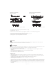
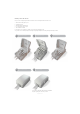
Mounting bracket (frame flat) -
Article No. 1015W1001:
Drawing No.: 1015W4001
Mounting bracket (frame flat) w/M4 nuts -
Article No. 1015W9009:
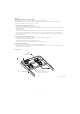
It is recommended to mount the QLCI2 in a position that allows water to escape.
Recommended torque: 0.6 Nm +/-0.1
The bracket can be mounted to the bed frame or any other application by means of one of the following mounting procedures:
1) M6 nut to be placed in bracket and fixed with M6 bolt from the rear side.
2) M5 machine screw with flat washer to be fixed through bracket with nut on the rear side.
3) Self-tapping screw to be placed through bracket and onto the frame.
Drawing No.: 1015W1009
Warnings:
• In general the load cells are not living up to 2 MOPP, which is okay as long as all other parts comply with 2 MOPP and the load cells are
electrically connected to the bed frame. This is to make the bed one electrical unit.
Recommendations
• Shielded load cell cables will be damaged if exposed to sharp bends. Therefore, if bended, cables should have a minimum bending radius of 60 mm.
• It is not allowed to bend load cell cables repeatedly, so mount cables on non-moving parts, like the bed frame.
• Load cell cables should not exceed a length of 2700 mm.
• In Europe weight systems are subject to important legal restrictions. The LINAK Weighing System system will be approved in accordance
with EN45501.
The used load cells must be OIML approved as well (this is not included in the LINAK approval).
• Do not mount the QLCI2 directly on actuators.
• Load cell cables are not to be mated more than 40 times.
Calibration and use
• When calibrating, the application and components should be allowed to acclimate to ensure that they have the same temperature as the
surrounding environment.
• For optimal performance the QLCI2 should be calibrated with a load similar to the in-use weight. For instance an application for lighter loads
would benefit from having the bed calibrated with a lighter calibration load than an application for heavy use.
• The application will be most precise when calibrated with a load slightly above the in-use weight.
• Calibrate the application on a stable base.
• While performing a zero or auto-compensation and the handheld control is not placed on the application, the weight of the attendant control is
not a part of the total weight. It leads to an incorrect measurement on the scale display, when the handheld control is placed on the application.
• When using auto-compensation or zeroing, do not touch the application or exert other external impacts on the application as this can result in
incorrect measurements.
• Be aware that while the handheld control is not placed on the application and if its cable is pulled, it can lead to incorrect measurement on the
scale display.