View Safety Info SVM 137-A CLASSIC III/IIID January, 1998 Gasoline & Diesel Engine Driven DC Arc Welding Power Source For use with machine code numbers 10061, 10072 or 10156. Return to Master TOC View Safety Info View Safety Info Safety Depends on You Return to Master TOC Return to Master TOC RETURN TO MAIN INDEX Lincoln arc welding and cutting equipment is designed and built with safety in mind. However, your overall safety can be increased by proper installation . . .
Return to Master TOC i i SAFETY WARNING CALIFORNIA PROPOSITION 65 WARNINGS Diesel engine exhaust and some of its constituents are known to the State of California to cause cancer, birth defects, and other reproductive harm. The Above For Diesel Engines The engine exhaust from this product contains chemicals known to the State of California to cause cancer, birth defects, or other reproductive harm. The Above For Gasoline Engines ARC WELDING CAN BE HAZARDOUS.
Return to Master TOC Return to Master TOC ii SAFETY ELECTRIC SHOCK can kill. ARC RAYS can burn. 3.a. The electrode and work (or ground) circuits are electrically “hot” when the welder is on. Do not touch these “hot” parts with your bare skin or wet clothing. Wear dry, hole-free gloves to insulate hands. 4.a. Use a shield with the proper filter and cover plates to protect your eyes from sparks and the rays of the arc when welding or observing open arc welding.
Return to Master TOC iii WELDING SPARKS can cause fire or explosion. 6.a. Remove fire hazards from the welding area. If this is not possible, cover them to prevent the welding sparks from starting a fire. Remember that welding sparks and hot materials from welding can easily go through small cracks and openings to adjacent areas. Avoid welding near hydraulic lines. Have a fire extinguisher readily available. 6.b.
Return to Master TOC Return to Master TOC Return to Master TOC Return to Master TOC iv iv SAFETY PRÉCAUTIONS DE SÛRETÉ Pour votre propre protection lire et observer toutes les instructions et les précautions de sûreté specifiques qui parraissent dans ce manuel aussi bien que les précautions de sûreté générales suivantes: Sûreté Pour Soudage A L’Arc 1. Protegez-vous contre la secousse électrique: a. Les circuits à l’électrode et à la piéce sont sous tension quand la machine à souder est en marche.
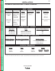
v v MASTER TABLE OF CONTENTS FOR ALL SECTIONS RETURN TO MAIN INDEX Page Safety .................................................................................................................................................i-iv Installation.............................................................................................................................Section A Technical Specifications .............................................................................................................
Return to Master TOC Section A-1 TABLE OF CONTENTS - INSTALLATION SECTION - Section A-1 Installation Technical Specifications ..............................................................................................................A-2 Safety Precautions ......................................................................................................................A-3 Location and Ventilation ......................................................................................................
Return to Master TOC A-2 INSTALLATION TECHNICAL SPECIFICATIONS - CLASSIC III AND IIID INPUT - ENGINE Manufacturer Description Classic III: Continental TM27 Classic IIID: Continental TMD27 Return to Master TOC Return to Section TOC Return to Section TOC A-2 4 cyl., 4 cycle Water-cooled Gasoline 38.9 HP @ 1700 RPM 4 cyl., 4 cycle Water-cooled Diesel 45 HP @ 1700 RPM Speed Displacement Ignition Capacities 1725 RPM Full load 164.7 cu. in. (2700 cc) Electric Fuel: 15 gal.
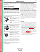
Return to Section TOC Return to Master TOC Return to Section TOC Return to Master TOC A-3 INSTALLATION Read this entire installation section before you start installation. SAFETY PRECAUTIONS WARNING Do not attempt to use this equipment until you have thoroughly read all the operation and maintenance manuals supplied with your machine. They include important safety precautions; detailed engine starting, operating, and maintenance instructions; and parts lists. ELECTRIC SHOCK can kill.
Return to Master TOC Return to Master TOC Return to Section TOC Return to Section TOC A-4 INSTALLATION STACKING WARNING Classic III and Classic IIID machines CANNOT be stacked. Keep hands away from the engine muffler or HOT engine parts. • Stop the engine when fueling. TILTING • Do not smoke when fueling. Place the machine on a secure, level surface whenever you use it or store it. Any surfaces you place it on other than the ground must be firm, non-skid, and structurally sound.
Return to Master TOC Return to Master TOC Return to Master TOC Return to Master TOC Return to Section TOC Return to Section TOC Return to Section TOC Return to Section TOC A-5 INSTALLATION A-5 COOLING SYSTEM TRAILER The cooling system has been filled at the factory with a 50-50 mixture of ethylene glycol antifreeze and water. Check the radiator level and add a 50-50 solution as needed. (See your engine manual or antifreeze container for alternate antifreeze recommendations.
Return to Master TOC Return to Section TOC A-6 A-6 INSTALLATION ELECTRICAL OUTPUT CONNECTIONS CAUTION See Figure A.1 for the location of the 115 and 230 volt receptacles, weld output terminals, and ground stud. • Loose connections will cause the output terminals to overheat. The terminals may eventually melt. • Do not cross the welding cables at the output terminal connection. Keep the cables isolated and separate from one another.
Return to Master TOC Return to Master TOC Return to Section TOC Return to Section TOC A-7 INSTALLATION MACHINE GROUNDING According to the United States National Electrical Code, the frame of this portable generator is not required to be grounded and is permitted to serve as the grounding means for cord connected equipment plugged into its receptacles. Some state, local or other codes or unusual operating circumstances may require the machine frame to be grounded.
Return to Section TOC Return to Master TOC Return to Section TOC Return to Master TOC Return to Master TOC Return to Section TOC Return to Master TOC Return to Section TOC A-8 NOTES Classic III and IIID A-8
Return to Master TOC Section B-1 Section B-1 TABLE OF CONTENTS - OPERATION SECTION Operation...............................................................................................................................Section B Safety Instructions.......................................................................................................................B-2 General Description ....................................................................................................................
Return to Master TOC Return to Section TOC B-2 OPERATION WARNING OPERATING INSTRUCTIONS Read and understand this entire section before operating your Classic III or Classic IIID. ENGINE EXHAUST can kill. SAFETY INSTRUCTIONS • Use in open, well ventilated areas or vent exhaust to the outside. WARNING • Do not stack anything on or near the engine.
Return to Master TOC Return to Section TOC B-3 OPERATION RECOMMENDED APPLICATIONS DESIGN FEATURES WELDER • All copper windings for long life and dependable operation. The Classic III and Classic IIID provide excellent constant current DC welding output for stick (SMAW) welding and for DC TIG welding. When equipped with the wire feed module, they also offer constant voltage output for DC semiautomatic wire feed welding.
Return to Master TOC OPERATION Return to Master TOC Return to Master TOC B-4 WELDING CAPABILITY LIMITATIONS The Classic III and Classic IIID are rated 300 amps, 32 volts constant current DC at 50% duty cycle based on a ten minute time period. Longer duty cycles at lower output currents are possible. The Classic III and Classic IIID are not recommended for any processes besides those that are normally performed using DC stick welding (SMAW) and DC TIG welding.
Return to Master TOC Return to Section TOC B-5 B-5 OPERATION CONTROLS AND SETTINGS The welder/generator controls are located on the Output Control Panel of the machine case front. Engine idler control and start/stop controls are also on the case front. Welding output terminals and ground stud are located on the machine left side, under the door. See Figures B.1, B.2 and B.3 and the explanations that follow. FIGURE B.
Return to Master TOC Return to Section TOC B-6 OPERATION CONTROL OF WELDING CURRENT A high open circuit voltage setting provides the soft "buttering" arc with best resistance to pop-outs preferred for most welding. To get this characteristic, set the CURRENT RANGE SELECTOR to the lowest setting that still provides the current you need and set the FINE CURRENT ADJUSTMENT near maximum.
FIGURE B.3 – GASOLINE ENGINE CONTROLS 60 Return to Master TOC Return to Master TOC Return to Master TOC Return to Section TOC 50 70 220 MAX 40 80 90 MIN 30 90 20 100 IDLER IGNITION OIL PRESSURE 230 VOLT AC Return to Section TOC 5 FINE CURRENT ADJUSTMENT CURRENT RANGE SELECTION 190-120 240-160 130-80 1. IDLER CONTROL TOGGLE SWITCH 2. IGNITION TOGGLE SWITCH 3. CHOKE 4. START PUSHBUTTON 5. ENGINE HOUR METER 6.
B-8 Return to Master TOC OPERATION FIGURE B.4 – DIESEL ENGINE CONTROLS 3 FINE CURRENT ADJUSTMENT CURRENT RANGE SELECTION 190-120 240-160 130-80 60 50 70 220 MAX 40 80 90 MIN 30 90 20 100 IDLER Return to Master TOC Return to Section TOC Return to Section TOC B-8 1. IDLER CONTROL TOGGLE SWITCH 2. IGNITION TOGGLE SWITCH 3. RESET BUTTON 4. START PUSHBUTTONS 5. ENGINE HOUR METER 6. OIL PRESSURE GAUGE 7. AMMETER 8.
Return to Master TOC Return to Master TOC Return to Section TOC Return to Section TOC B-9 OPERATION STARTING THE CLASSIC III CONTINENTAL TM27 GASOLINE ENGINE ENGINE OPERATION WARNING NOTE: Remove all loads connected to the AC power receptacles before starting the engine. DO NOT RUN THE ENGINE AT EXCESSIVE SPEEDS. The maximum allowable high idle speed for the Classic III and Classic IIID is 1800 RPM, no load. Do NOT increase the idle speed on the engine.
Return to Master TOC Return to Master TOC Return to Section TOC Return to Section TOC B-10 B-10 OPERATION STOPPING THE ENGINE (GASOLINE OR DIESEL) BREAK-IN PERIOD 1. Place the IGNITION switch in the OFF position. At the end of each day’s welding, drain accumulated dirt and water from the sediment bowl under the fuel tank and from the fuel filter (diesel engine, Classic IIID) per instructions in the engine manufacturer’s operating manual.
Return to Master TOC Return to Section TOC B-11 OPERATION WELDING OPERATION TO USE THE CLASSIC III OR CLASSIC IIID FOR DC CONSTANT CURRENT STICK OR TIG WELDING: After you finish welding: 1. Remove the flange nuts from the weld output terminals and place the work and electrode welding cables over the terminals. See Figure B.5. Replace and tighten the flange nuts securely. Be sure the connections are tight. 1. Stop the engine. See Engine Operation in this section of the manual. 2.
Return to Master TOC Return to Section TOC B-12 B-12 OPERATION TO USE THE CLASSIC III OR CLASSIC IIID FOR DC WIRE FEED WELDING (CONSTANT VOLTAGE WITH WIRE FEED MODULE): 1. Connect the LN-25, LN-23P, or LN-7 Wire Feeder. Follow the installation instructions provided with the wire feeder. 2. Set the machine for CV operation. 3. Start the engine. See Engine Operation in this section of the manual. Return to Master TOC Return to Section TOC 4. Set the Idler Switch to "AUTO." 5.
Return to Master TOC Return to Section TOC B-13 OPERATION AUXILIARY POWER WARNING To use the generator as an auxiliary power supply: Be sure that any electrical equipment plugged into the generator AC power receptacles can withstand a ±10% voltage and a ±3% frequency variation. Return to Master TOC Return to Section TOC 1. Start the diesel engine. See Engine Operation in this section of the manual. 2. Set the IDLER switch to AUTO. Set the CURRENT RANGE SELECTOR to “MAX.” See Figure B.1.
Return to Section TOC Return to Master TOC Return to Section TOC Return to Master TOC Return to Master TOC Return to Section TOC Return to Master TOC Return to Section TOC B-14 NOTES Classic III and IIID B-14
Return to Master TOC Section C-1 Section C-1 TABLE OF CONTENTS - ACCESSORIES Accessories...........................................................................................................................Section C Options/Accessories ...................................................................................................................C-2 TIG Welding Accessories............................................................................................................
Return to Master TOC Return to Section TOC C-2 ACCESSORIES OPTIONS/ACCESSORIES The following options/accessories are available for your Classic III or Classic IIID from your local Lincoln Distributor. Trailer (K913) - Two-wheeled trailer for in-plant and yard towing. Various hitches and accessories are available. For highway use, consult applicable federal, state, and local laws. C-2 Wire Feed Module - (K623-1) - Provides constant voltage output for semiautomatic welding.
Return to Master TOC Return to Section TOC C-3 ACCESSORIES C-3 TIG WELDING ACCESSORIES SEMIAUTOMATIC WELDING ACCESSORIES K930-2 TIG Module - The TIG Module is an accessory that provides high frequency & shielding gas control for DC GTAW (TIG) welding applications. LN-25 Wire Feeder - This portable wire feeder is capable of CC/CV wire feed welding. The TIG Module is supplied without accessories. Arc start switches, amptrols, cables, torches and mounting brackets must be purchased separately.
Return to Master TOC Return to Section TOC C-4 ACCESSORIES CONNECTION OF LINCOLN ELECTRIC WIRE FEEDERS CONNECTION OF THE LN-7 TO THE CLASSIC III OR CLASSIC IIID (EQUIPPED WITH K623-1 WIRE FEED MODULE) USING K867 UNIVERSAL ADAPTER (SEE FIGURE C.1.) 4. Connect the K291 or K404 input cable to the LN-7. 5. Place the IDLER switch in the “HIGH” position.
Return to Master TOC Return to Section TOC C-5 ACCESSORIES CONNECTION OF THE LN-7 TO THE CLASSIC III OR CLASSIC IIID (EQUIPPED WITH K623-1 WIRE FEED MODULE) USING K584 INPUT CABLE ASSEMBLY (SEE FIGURE C.2.) 1. Shut the welder off. 2. Connect the electrode cable from the LN-7 to the “+” terminal of the welder. Connect the work cable to the “CV-” terminal of the welder. Return to Master TOC NOTE: Welding cable must be sized for current and duty cycle of application.
Return to Master TOC Return to Section TOC C-6 ACCESSORIES CONNECTION OF THE LN-25 TO THE CLASSIC III OR CLASSIC IIID (EQUIPPED WITH K623-1 WIRE FEED MODULE) USING K867 UNIVERSAL ADAPTER (SEE FIGURE C.3.) 4. Connect the K432-L cable to the LN-25 equipped with the K431-1 remote output control kit. 5. Place the IDLER switch in the “HIGH” position. CAUTION 1. Shut the welder off. 2. Connect the electrode cable from the LN-25 to the “+” terminal of the welder.
Return to Master TOC Return to Section TOC C-7 ACCESSORIES CONNECTION OF THE LN-25 TO THE CLASSIC III OR CLASSIC IIID (EQUIPPED WITH K623-1 WIRE FEED MODULE) “ACROSS THE ARC” (SEE FIGURE C.4.) 1. Shut the welder off. 2. Connect the electrode cable from the LN-25 to the “+” terminal of the welder. Connect the work cable to the “CV–” terminal of the welder.
Return to Master TOC Return to Section TOC C-8 INSTALLATION 6. Connect control lead marked “21” to the work as indicated in Figure C.5. CONNECTION OF THE LN-23P TO THE CLASSIC III OR CLASSIC IIID (EQUIPPED WITH K623-1 WIRE FEED MODULE) USING THE K-350-1 ADAPTER KIT (SEE FIGURE C.5) 7. Set the CURRENT RANGE SELECTOR switch to the 190-120 (middle) position for most common processes. This may be changed if a different arc characteristic is preferred. 1. Shut the welder off. 8.
Return to Master TOC Return to Section TOC C-9 ACCESSORIES CONNECTION OF THE K488 SG CONTROL MODULE AND K487 MAGNUM SPOOL GUN TO THE CLASSIC III OR CLASSIC IIID (EQUIPPED WITH K623-1 WIRE FEED MODULE) (SEE FIGURE C.6.) 6. Place the IDLER switch on the Classic III or Classic IIID in the “HIGH” position. 1. Shut the welder off. Any increase of the high idle engine RPM by changing the governor setting or overriding the throttle linkage will cause an increase in the AC auxiliary voltage.
Return to Section TOC Return to Master TOC Return to Section TOC Return to Master TOC Return to Master TOC Return to Section TOC Return to Master TOC Return to Section TOC C-10 NOTES Classic III and IIID C-10
Return to Master TOC Section D-1 Section D-1 TABLE OF CONTENTS -MAINTENANCEMaintenance .........................................................................................................................Section D Safety Precautions ......................................................................................................................D-2 Routine and Periodic Maintenance .............................................................................................D-2 Engine Maintenance..
Return to Master TOC Return to Section TOC D-2 MAINTENANCE SAFETY PRECAUTIONS ROUTINE AND PERIODIC MAINTENANCE WARNING ENGINE MAINTENANCE • Have qualified personnel do all maintenance and troubleshooting work. • Turn the engine off before working inside the machine. • Remove covers or guards only when necessary to perform maintenance and replace them when the maintenance requiring their removal is complete.
Return to Master TOC Return to Section TOC D-3 D-3 MAINTENANCE FIGURE D.1 – OIL DRAIN AND REFILL 2 5 Return to Master TOC Return to Master TOC Return to Section TOC Return to Section TOC 4 1. 2. 3. 4. 5. 3 1 CHANGE THE OIL FILTER: Change the oil filter the first time between 25 and 50 hours of operation. Then, under normal operating conditions, change the oil filter per Table D.1 or consult your engine Owner’s Manual.
Return to Master TOC Return to Section TOC D-4 MAINTENANCE FUEL FILTER - DIESEL ENGINE (CLASSIC IIID CODES ABOVE 10061 WITH STANADYNE FUEL FILTER): The diesel engine fuel filter is a metal canister element type. It cannot be cleaned. Replace the filter per Table D.1 or if there is reason to believe it is plugged. Change the fuel filter as follows: 1. See Figure D.2. Release the two spring clamps (1). 2. Pull the old element (2) off the filter bracket. 3.
Return to Master TOC Return to Section TOC D-5 D-5 MAINTENANCE HOW TO ELIMINATE AIR FROM THE FUEL SYSTEM – DIESEL ENGINE (CLASSIC IIID) The following procedure is for Classic IIID diesel engines with a Stanadyne type fuel filter (Figure D.2). If your filter is different, refer to your engine Owner’s Manual for the correct procedure for eliminating air from the system. 1. Set the IDLER switch to HIGH and turn the ignition switch ON. Return to Master TOC Return to Section TOC 2. See Figure D.3.
Return to Section TOC Return to Master TOC Return to Section TOC Return to Master TOC D-6 MAINTENANCE FIGURE D.4 – ENGINE COOLANT DRAIN PLUG AND RADIATOR DRAIN COCK COOLING SYSTEM: The Continental engine, gasoline or diesel, is water cooled. Check the coolant level at the radiator filler daily. Add a 50-50 mixture of water and antifreeze as needed. To drain and refill the system, do the following: 1. Ensure that the machine is on level ground.
Return to Master TOC Return to Section TOC D-7 D-7 MAINTENANCE TIGHTENING THE FAN BELT: Fan belts tend to loosen after the first 50 hours of operation. If the fan belts are loose, the engine can overheat and the battery can lose its charge. Check belt tightness by pressing on the belt midway between the pulleys. The belt should deflect no more than 13 mm (0.5 in.). See Figure D.6. To adjust the fan belt, do the following: 2. Change the position of the alternator to give the correct tension.
Return to Master TOC Return to Section TOC D-8 MAINTENANCE TABLE D.
Return to Master TOC Return to Section TOC D-9 MAINTENANCE BATTERY MAINTENANCE WARNING GASES FROM BATTERY can explode. • Keep sparks, flame, and cigarettes away from battery. D-9 CHECKING SPECIFIC GRAVITY Check each battery cell with a hydrometer. A fully charged battery will have a specific gravity of 1.260. Charge the battery if the reading is below 1.215. NOTE: Correct the specific gravity reading by adding four gravity points (0.
Return to Master TOC Return to Section TOC D-10 MAINTENANCE WELDER/GENERATOR MAINTENANCE tion, stone slip ring with a fine stone. Brushes must be seated 100%. STORAGE: Store the Classic III or Classic IIID in clean, dry, protected areas. CLEANING: Blow out the generator and controls periodically with low pressure air. Do this at least once a week in particularly dirty areas.
Return to Master TOC Return to Section TOC D-11 MAINTENANCE IDLER MAINTENANCE 1. The solenoid plunger must work freely because binding can cause engine surging. If surging occurs, be sure the plunger is properly lined up with the throttle lever. Dust the plunger about once a year with graphite powder. 2. When any service is done, reassemble the rubber bellows on the solenoid plunger with the vent hole on the lower side.
Return to Section TOC Return to Master TOC Return to Section TOC Return to Master TOC D-12 MAINTENANCE FIGURE D.7 - MAJOR COMPONENT LOCATIONS (CLASSIC IIID SHOWN) 1. 2. 3. 4. 5. 6. 7. 8. 9. 10. 11. 12. 13. 14. 15.
Return to Section TOC Return to Master TOC Return to Section TOC Return to Master TOC Return to Master TOC Return to Section TOC Return to Master TOC Return to Section TOC D-13 NOTES Classic III and IIID D-13
Return to Section TOC Return to Master TOC Return to Section TOC Return to Master TOC Return to Master TOC Return to Section TOC Return to Master TOC Return to Section TOC D-14 NOTES Classic III and IIID D-14
Return to Master TOC Section E-1 Section E-1 TABLE OF CONTENTS -THEORY OF OPERATION SECTIONTheory of Operation .............................................................................................................Section E General Description ...............................................................................................................E-2 Battery, Starter, Engine Alternator and Oil Switch Circuits (Classic III) ................................
Return to Section TOC Return to Master TOC Return to Section TOC Return to Master TOC E-2 THEORY OF OPERATION GENERAL DESCRIPTION The Classic III and Classic IIID are heavy duty, engine driven, DC arc welding power sources capable of providing constant current output for stick welding or DC TIG welding. Also, a total of 3000 watts of auxiliary power is available at the 115 or 230VAC receptacles. The Classic III and Classic IIID models are manufactured with all copper windings. FIGURE E.
Return to Master TOC Return to Master TOC Return to Master TOC Return to Master TOC Return to Section TOC Return to Section TOC Return to Section TOC Return to Section TOC E-3 THEORY OF OPERATION E-3 FIGURE E.2a – BATTERY, STARTER, ENGINE ALTERNATOR AND OIL SWITCH CIRCUIT (CLASSIC III) BATTERY, STARTER, ENGINE ALTERNATOR AND OIL SWITCH CIRCUIT (CLASSIC III) The 12VDC battery powers the starter motor and, through the ignition switch, the engine ignition and fuel shutoff solenoid.
Return to Master TOC Return to Master TOC Return to Master TOC Return to Master TOC Return to Section TOC Return to Section TOC Return to Section TOC Return to Section TOC E-4 THEORY OF OPERATION FIGURE E.2b – BATTERY, STARTER, ENGINE ALTERNATOR AND ENGINE PROTECTION CIRCUITRY (CLASSIC IIID) BATTERY, STARTER, ENGINE ALTERNATOR AND PROTECTION CIRCUITRY (CLASSIC IIID) The 12VDC battery powers the starter motor, glow plugs and the engine protection circuitry.
Return to Master TOC Return to Master TOC Return to Master TOC Return to Master TOC Return to Section TOC Return to Section TOC Return to Section TOC Return to Section TOC E-5 THEORY OF OPERATION E-5 FIGURE E.3 – ENGINE, GENERATOR ARMATURE AND FRAME, ALTERNATOR STATOR AND ROTOR (CLASSIC III) NOTE: Unshaded areas of Block Logic Diagram are the subject of discussion.
Return to Master TOC Return to Section TOC E-6 THEORY OF OPERATION CURRENT RANGE SELECTOR ENGINE IDLER CIRCUIT The selector switch acts as a coarse current adjustment by allowing varying amounts of series windings to be included in the welding current path. The series coils and selector switch are connected in series with the negative output terminal. The idler solenoid is mechanically connected to the engine governor linkage. When welding current is being drawn, the reed switch CR2 is closed.
Return to Master TOC Return to Section TOC E-7 THEORY OF OPERATION FIGURE E.
Return to Section TOC Return to Master TOC Return to Section TOC Return to Master TOC Return to Master TOC Return to Section TOC Return to Master TOC Return to Section TOC E-8 NOTES Classic III and IIID E-8
Return to Master TOC Section F-1 Section F-1 TABLE OF CONTENTS TROUBLESHOOTING & REPAIR SECTION Troubleshooting & Repair Section.................................................................................Section F How to Use Troubleshooting Guide .......................................................................................F-2 PC Board Troubleshooting Procedures..................................................................................F-3 Troubleshooting Guide .......................
Return to Master TOC Return to Master TOC Return to Master TOC Return to Section TOC Return to Section TOC Return to Section TOC F-2 TROUBLESHOOTING & REPAIR HOW TO USE TROUBLESHOOTING GUIDE WARNING Service and repair should be performed by only Lincoln Electric Factory Trained Personnel. Unauthorized repairs performed on this equipment may result in danger to the technician and machine operator and will invalidate your factory warranty.
Return to Master TOC Return to Section TOC F-3 TROUBLESHOOTING & REPAIR F-3 PC BOARD TROUBLESHOOTING PROCEDURES WARNING ELECTRIC SHOCK can kill. Have an electrician install and service this equipment. Turn the machine OFF before working on equipment. Do not touch electrically hot parts. • Remove the PC Board from the static-shielding bag and place it directly into the equipment. Don’t set the PC Board on or near paper, plastic or cloth which could have a static charge.
Return to Master TOC Return to Section TOC F-4 TROUBLESHOOTING & REPAIR Observe Safety Guidelines detailed in the beginning of this manual. TROUBLESHOOTING GUIDE PROBLEMS (SYMPTOMS) RECOMMENDED COURSE OF ACTION Return to Master TOC Return to Master TOC Return to Master TOC Return to Section TOC Return to Section TOC POSSIBLE AREAS OF MISADJUSTMENT(S) OUTPUT PROBLEMS The engine starts and runs at correct speed, but there is no, or very low, welder output voltage.
Return to Master TOC TROUBLESHOOTING GUIDE PROBLEMS (SYMPTOMS) Observe Safety Guidelines detailed in the beginning of this manual. POSSIBLE AREAS OF MISADJUSTMENT(S) Return to Master TOC Return to Master TOC RECOMMENDED COURSE OF ACTION OUTPUT PROBLEMS 1. Check for loose or missing brushes in the welding generator. 2. Check the welding cables for loose or faulty connections. 1. Check the Fine Current Adjustment rheostat for resistance and proper operation. Normal resistance is 64 ohms.
Return to Master TOC Return to Section TOC F-6 TROUBLESHOOTING & REPAIR TROUBLESHOOTING GUIDE Observe Safety Guidelines detailed in the beginning of this manual. PROBLEMS (SYMPTOMS) POSSIBLE AREAS OF MISADJUSTMENT(S) Return to Master TOC RECOMMENDED COURSE OF ACTION OUTPUT PROBLEMS The welding output varies abnormally. The auxiliary output remains constant. The engine is operating correctly. 1. May be a normal condition. The machine will normally lose some output as the components get heated. 2.
Return to Master TOC Return to Master TOC Return to Master TOC Return to Master TOC Return to Section TOC Return to Section TOC Return to Section TOC Return to Section TOC F-7 TROUBLESHOOTING & REPAIR TROUBLESHOOTING GUIDE PROBLEMS (SYMPTOMS) F-7 Observe Safety Guidelines detailed in the beginning of this manual. POSSIBLE AREAS OF MISADJUSTMENT(S) RECOMMENDED COURSE OF ACTION OUTPUT PROBLEMS The engine starts and runs at the correct speed, but there is no AC auxiliary output voltage.
Return to Master TOC Return to Section TOC F-8 TROUBLESHOOTING & REPAIR Observe Safety Guidelines detailed in the beginning of this manual. TROUBLESHOOTING GUIDE PROBLEMS (SYMPTOMS) RECOMMENDED COURSE OF ACTION POSSIBLE AREAS OF MISADJUSTMENT(S) FUNCTION PROBLEMS The engine will not return to low idle when the welding and auxiliary loads are removed. 1. Make sure the Idler Control switch is set to the “Auto” position. Return to Master TOC 2.
Return to Master TOC TROUBLESHOOTING & REPAIR TROUBLESHOOTING GUIDE PROBLEMS (SYMPTOMS) Return to Master TOC Return to Master TOC F-9 Observe Safety Guidelines detailed in the beginning of this manual. POSSIBLE AREAS OF MISADJUSTMENT(S) RECOMMENDED COURSE OF ACTION FUNCTION PROBLEMS The engine will NOT go to high speed when a load is applied to the welding output terminals. The engine does go to high speed when a load is applied to the AC auxiliary power receptacles. 1.
Return to Master TOC Return to Master TOC Return to Master TOC Return to Master TOC Return to Section TOC Return to Section TOC Return to Section TOC Return to Section TOC F-10 TROUBLESHOOTING & REPAIR F-10 Observe Safety Guidelines detailed in the beginning of this manual.
Return to Master TOC Return to Section TOC F-11 TROUBLESHOOTING & REPAIR TROUBLESHOOTING GUIDE PROBLEMS (SYMPTOMS) POSSIBLE AREAS OF MISADJUSTMENT(S) 1. Check for adequate fuel supply. 2. Make sure the ignition switch is in the “ON” position. 1. Check for adequate fuel supply. 2. Make sure the ignition switch is in the “ON” position. Return to Master TOC 3. Press the glow plug button for 10 to 20 seconds. Return to Master TOC 1. Check the ignition switch for proper operation.
Return to Master TOC Return to Section TOC F-12 TROUBLESHOOTING & REPAIR TROUBLESHOOTING GUIDE PROBLEMS (SYMPTOMS) Observe Safety Guidelines detailed in the beginning of this manual. POSSIBLE AREAS OF MISADJUSTMENT(S) 1. Check for adequate fuel supply. 2. Check the engine oil level. 1. The Classic IIID diesel only: The oil pressure switch or temperature sensor may be causing the engine protection relay to shut off the fuel supply to the engine. 2. The protection relay may be faulty.
Return to Master TOC Return to Section TOC F-13 TROUBLESHOOTING & REPAIR TROUBLESHOOTING GUIDE PROBLEMS (SYMPTOMS) Return to Master TOC Return to Section TOC Observe Safety Guidelines detailed in the beginning of this manual. POSSIBLE AREAS OF MISADJUSTMENT(S) The welding arc frequently “pops out.” 1. The current setting may be too high for the electrode and process. 1. Check the engine speed. High idle speed should be 1800 RPM. 2. The polarity may be wrong for the electrode and process. 2.
Return to Master TOC Return to Master TOC Return to Section TOC Return to Section TOC F-14 TROUBLESHOOTING & REPAIR ALTERNATOR ROTOR TEST WARNING Service and repair should be performed by only Lincoln Electric factory trained personnel. Unauthorized repairs performed on this equipment may result in danger to the technician or machine operator and will invalidate your factory warranty.
Return to Master TOC Return to Section TOC F-15 TROUBLESHOOTING & REPAIR F-15 ALTERNATOR ROTOR TEST (continued) FIGURE F.1 – ALTERNATOR COVER REMOVAL WRAPAROUND Return to Master TOC Return to Section TOC SLIP RINGS ALTERNATOR COVER BRUSHES Return to Section TOC Return to Master TOC Return to Section TOC Return to Master TOC TEST PROCEDURE 1. Turn engine off. 2. With the 3/8" nut driver or socket wrench, loosen the screws on the left and right sides and bottom of the alternator wraparound.
Return to Master TOC Return to Section TOC F-16 TROUBLESHOOTING & REPAIR ALTERNATOR ROTOR TEST (continued) 6. Working from the left side of the machine, measure the resistance across the rotor slip rings. a. Set the ohmmeter on the low scale (X1). b. Place one meter probe on one of the rotor slip rings. Place the other probe on the other slip ring. See Figure F.2. Return to Master TOC Return to Section TOC c. Check the resistance across the slip rings. It should read approximately 41 ohms.
Return to Master TOC Return to Section TOC F-17 TROUBLESHOOTING & REPAIR ALTERNATOR ROTOR TEST (continued) 7. Measure the rotor resistance to ground. a. Set the ohmmeter on the high scale (X100,000). sure they are seated correctly. 9. Reinstall the alternator cover and wraparound. b. Place one probe on either of the rotor slip rings. Place the other probe on any good, unpainted ground. See Figure F.3.
Return to Master TOC Return to Section TOC F-18 TROUBLESHOOTING & REPAIR FIELD SHUNT WINDING TEST WARNING Service and repair should be performed by only Lincoln Electric factory trained personnel. Unauthorized repairs performed on this equipment may result in danger to the technician or machine operator and will invalidate your factory warranty. For your safety and to avoid electrical shock, please observe all safety notes and precautions detailed throughout this manual.
Return to Master TOC Return to Section TOC F-19 TROUBLESHOOTING & REPAIR F-19 FIELD SHUNT WINDING TEST (continued) FIGURE F.4 – PLUG P10 LOCATIONS Return to Master TOC Return to Section TOC PLUG P10 TEST PROCEDURE 1. Turn engine off. Return to Section TOC Return to Master TOC Return to Section TOC Return to Master TOC 2. Unlatch, lift and secure the left side door. Note that there are latches at both ends of the door. 4.
Return to Master TOC Return to Section TOC F-20 TROUBLESHOOTING & REPAIR F-20 FIELD SHUNT WINDING TEST (continued) FIGURE F.5 – SHUNT LEAD RESISTANCE CHECK PIN 3 Return to Master TOC Return to Section TOC PIN 5 Return to Master TOC Return to Section TOC TAB 8. If the plug and associated leads are okay, then the shunt field coils may be faulty. Replace. 5. Using the volt/ohmmeter set on the low scale (X1), measure the resistance between the blue and the brown leads. See Figure F.5.
Return to Master TOC Return to Section TOC F-21 TROUBLESHOOTING & REPAIR FLASHING THE FIELDS WARNING Service and repair should be performed by only Lincoln Electric factory trained personnel. Unauthorized repairs performed on this equipment may result in danger to the technician or machine operator and will invalidate your factory warranty. For your safety and to avoid electrical shock, please observe all safety notes and precautions detailed throughout this manual.
Return to Section TOC Return to Master TOC Return to Section TOC Return to Master TOC F-22 F-22 TROUBLESHOOTING & REPAIR FLASHING THE FIELDS (continued) FIGURE F.6 - FLASHING THE FIELDS NEGATIVE (-) BRUSH HOLDER _ + POSITIVE (+) BRUSH HOLDER 12 VOLT BATTERY Return to Master TOC Return to Section TOC PROCEDURE 1. Turn engine OFF. 2. Remove the cover from the exiter. Figure F.6. See 3. Turn the FINE CURRENT ADJUSTMENT control (rheostat) to “100.” 4.
Return to Master TOC Return to Section TOC F-23 TROUBLESHOOTING & REPAIR IDLER SOLENOID TEST WARNING Service and repair should be performed by only Lincoln Electric factory trained personnel. Unauthorized repairs performed on this equipment may result in danger to the technician or machine operator and will invalidate your factory warranty. For your safety and to avoid electrical shock, please observe all safety notes and precautions detailed throughout this manual.
Return to Master TOC Return to Section TOC F-24 TROUBLESHOOTING & REPAIR F-24 IDLER SOLENOID TEST (continued) FIGURE F.7 - SOLENOID LEAD CONNECTIONS LEADS 56 & 57 Return to Master TOC Return to Section TOC SOLENOID TEST PROCEDURE 6. The solenoid should deactivate when the 12VDC is removed. Return to Master TOC Return to Section TOC 1. Turn engine off. 2. Unlatch, lift and secure the left side door. Note that there are latches at both ends of the door. 3.
Return to Master TOC Return to Section TOC F-25 TROUBLESHOOTING & REPAIR ENGINE THROTTLE ADJUSTMENT TEST - CLASSIC IIID (DIESEL) WARNING Return to Master TOC Return to Section TOC Service and repair should be performed by only Lincoln Electric factory trained personnel. Unauthorized repairs performed on this equipment may result in danger to the technician or machine operator and will invalidate your factory warranty.
Return to Master TOC Return to Master TOC Return to Master TOC Return to Section TOC Return to Section TOC Return to Section TOC F-26 TROUBLESHOOTING & REPAIR ENGINE THROTTLE ADJUSTMENT TEST (continued) FIGURE F.8 - STROBE MARK LOCATION STROBE MARK TEST PROCEDURE 5. Start the engine and direct the strobe-tach light on the blower paddle. Synchronize it to the rotating mark. Strobe Tach Method 1. Turn the engine welder OFF. 2. Unlatch, lift and secure the left side door.
Return to Master TOC TROUBLESHOOTING & REPAIR 6. If either of the readings is incorrect, adjust the throttle as follows: Adjust LOW IDLE: First make sure there is no load on the machine. Set the IDLE switch to AUTO and wait for the engine to change to low idle speed. Use the 7/16" wrench to loosen the solenoid lever arm locking nut. See Figure F.10. Adjust the threaded solenoid lever arm shaft, to change the amount of throw in the lever arm, until the tach reads between 1325 and 1475 RPM.
Return to Section TOC Return to Master TOC Return to Section TOC Return to Master TOC F-28 TROUBLESHOOTING & REPAIR ENGINE THROTTLE ADJUSTMENT TEST (continued) FIGURE F.9 - HIGH IDLE ADJUSTMENT ADJUSTING SCREW LOCKING NUT Return to Master TOC Return to Section TOC FIGURE F.
Return to Master TOC Return to Section TOC F-29 TROUBLESHOOTING & REPAIR ENGINE THROTTLE ADJUSTMENT TEST - CLASSIC III (GASOLINE) WARNING Return to Master TOC Return to Section TOC Service and repair should be performed by only Lincoln Electric factory trained personnel. Unauthorized repairs performed on this equipment may result in danger to the technician or machine operator and will invalidate your factory warranty.
Return to Master TOC Return to Master TOC Return to Master TOC Return to Master TOC Return to Section TOC Return to Section TOC Return to Section TOC Return to Section TOC F-30 TROUBLESHOOTING & REPAIR F-30 ENGINE THROTTLE ADJUSTMENT TEST (continued) FIGURE F.11 - BLOWER PADDLE MARK LOCATION STROBE MARK TEST PROCEDURE STROBE TACH METHOD 1. Conduct this procedure with the engine OFF. 2. Unlatch, lift, and secure the right and left side doors. 4.
Return to Master TOC Return to Section TOC F-31 TROUBLESHOOTING & REPAIR 6. If either of these readings is incorrect, adjust the throttle as follows: Adjust High Idle a. Make sure there is no load on the machine. b. Set the Idler switch to the HIGH position. c. Locate the governor on the left side of the engine. See Figure F.12. d. Using the 3/8” wrench to turn the adjustment screw and locking nut, adjust the high idle speed to between 1780 - 1810 RPM. It may not be necessary to remove the seal.
Return to Master TOC Return to Section TOC F-32 TROUBLESHOOTING & REPAIR OSCILLOSCOPE METHOD Adjust Low Idle 1. Connect the oscilloscope to the 115 VAC receptacle, according to the manufacturer's instructions. At HIGH IDLE (1800 RPM), the waveform should exhibit a period of 16.6 milliseconds. At LOW IDLE (1400 RPM), the waveform should exhibit a period of 21.4 milliseconds. Refer to the NORMAL OPEN CIRCUIT VOLTAGE WAVEFORM (115 VAC SUPPLY) HIGH IDLE - NO LOAD in this section of the manual. a.
Return to Section TOC Return to Master TOC Return to Section TOC Return to Master TOC Return to Master TOC Return to Section TOC Return to Master TOC Return to Section TOC F-33 INSTALLATION ENGINE THROTTLE ADJUSTMENT TEST (continued) FIGURE F.
Return to Master TOC Return to Section TOC F-34 F-34 TROUBLESHOOTING & REPAIR NORMAL OPEN CIRCUIT VOLTAGE WAVEFORM (115VAC SUPPLY) HIGH IDLE – NO LOAD – FINE CURRENT CONTROL RHEOSTAT AT MAXIMUM 16.6 ms Return to Master TOC Return to Section TOC CH1 0 volts Return to Master TOC Return to Section TOC 50 volts This is the typical auxiliary output voltage generated from a properly operating machine.
Return to Master TOC Return to Section TOC F-35 F-35 TROUBLESHOOTING & REPAIR NORMAL OPEN CIRCUIT DC WELD VOLTAGE WAVEFORM HIGH IDLE – NO LOAD – FINE CURRENT CONTROL RHEOSTAT AND SELECTOR SWITCH AT MAXIMUM Return to Master TOC Return to Section TOC CH1 0 volts Return to Master TOC Return to Section TOC 50 volts This is the typical DC output voltage generated from a properly operating machine.
Return to Master TOC Return to Section TOC F-36 TROUBLESHOOTING & REPAIR TYPICAL DC WELD OUTPUT VOLTAGE WAVEFORM MACHINE LOADED – SELECTOR SWITCH AT MAXIMUM POSITION Return to Master TOC Return to Section TOC CH1 0 volts 20 volts 5 ms Return to Master TOC Return to Section TOC MACHINE LOADED TO 250 AMPS AT 40 VDC This is the typical DC output voltage generated from a properly operating machine.
Return to Master TOC Return to Section TOC F-37 TROUBLESHOOTING & REPAIR ALTERNATOR ROTOR REMOVAL AND REPLACEMENT WARNING Service and repair should be performed by only Lincoln Electric factory trained personnel. Unauthorized repairs performed on this equipment may result in danger to the technician or machine operator and will invalidate your factory warranty. For your safety and to avoid electrical shock, please observe all safety notes and precautions detailed throughout this manual.
Return to Master TOC Return to Section TOC F-38 TROUBLESHOOTING & REPAIR ALTERNATOR ROTOR REMOVAL AND REPLACEMENT (continued) PROCEDURE 1. Turn the engine off. 2. Using the 7/16” wrench, remove the two bolts and washers and partially slide out the battery mounting panel. See Figure F.14 Return to Master TOC Return to Master TOC Return to Master TOC Return to Section TOC Return to Section TOC Return to Section TOC 3. With the 1/2" wrench, disconnect the negative battery cable. FIGURE F.
Return to Master TOC Return to Section TOC F-39 TROUBLESHOOTING & REPAIR ALTERNATOR ROTOR REMOVAL AND REPLACEMENT (continued) See Figure F.15 for steps 3 - 5. 3. With the 3/8" wrench, loosen the screws on the left and right sides and bottom of the alternator wrap-around. 4. With the 5/16" wrench, remove the 4 screws from the alternator cover. Return to Master TOC Return to Section TOC 5. Remove the alternator cover and wraparound. Be careful to clear the leads. FIGURE F.
Return to Master TOC Return to Section TOC F-40 TROUBLESHOOTING & REPAIR ALTERNATOR ROTOR REMOVAL AND REPLACEMENT (continued) See Figure F.16 for steps 6 - 8. 6. With the 7/16" wrench, remove the two bolts, nuts and washers mounting the brush holder assembly to the stator frame. Return to Section TOC Return to Master TOC Return to Section TOC Return to Master TOC 7. Bend the flat washer away from the rotor locking nut. Return to Master TOC 8.
Return to Master TOC Return to Section TOC F-41 INSTALLATION ALTERNATOR ROTOR REMOVAL AND REPLACEMENT (continued) Replacement d. The exciter brush spring must lie flat on the corner of the brush and not touch either side of the retainer. 9. Carefully mount the rotor onto the generator shaft. Install a new sleeve collar (part number T14337), washer, and rotor locking nut. e.
Return to Master TOC Return to Section TOC F-42 TROUBLESHOOTING & REPAIR ALTERNATOR STATOR REMOVAL AND REPLACEMENT WARNING Service and repair should be performed by only Lincoln Electric factory trained personnel. Unauthorized repairs performed on this equipment may result in danger to the technician or machine operator and will invalidate your factory warranty. For your safety and to avoid electrical shock, please observe all safety notes and precautions detailed throughout this manual.
Return to Section TOC Return to Master TOC Return to Section TOC Return to Master TOC F-43 TROUBLESHOOTING & REPAIR F-43 ALTERNATOR STATOR REMOVAL AND REPLACEMENT (continued) FIGURE F.17 – COMMUTATOR WRAP-AROUND REMOVAL COMMUTATOR WRAPAROUND ALTERNATOR BRUSH HOLDER ASSEMBLY (REMOVED) PROCEDURE 1. Turn the engine OFF. 8. Remove the tape and using the 3/8" wrench and slot head screw driver, disconnect the black auxiliary power lead from the current transformer. Cut any necessary cable ties.
Return to Master TOC Return to Master TOC Return to Section TOC Return to Section TOC F-44 TROUBLESHOOTING & REPAIR F-44 ALTERNATOR STATOR REMOVAL AND REPLACEMENT (continued) FIGURE F.18 - LEAD DISCONNECTION POINTS YELLOW AND WHITE WIRE IN-LINE CONNECTORS; YELLOW LEADS; BLACK CURRENT TRANSFORMER LEAD ALL LOCATED BEHIND CASE FRONT Return to Master TOC Return to Section TOC FIGURE F.
Return to Master TOC Return to Section TOC F-45 TROUBLESHOOTING & REPAIR ALTERNATOR STATOR REMOVAL AND REPLACEMENT (continued) 13. Clear the leads in preparation for removing the stator/end bracket. 14. Lift the eight brushes from the commutator. Note the position of the brushes for reassembly. Return to Section TOC Return to Master TOC Return to Section TOC Return to Master TOC Return to Master TOC FIGURE F.
TROUBLESHOOTING & REPAIR Return to Master TOC Return to Section TOC F-46 F-46 ALTERNATOR STATOR REMOVAL AND REPLACEMENT (continued) FIGURE F.21 - DRILL SPOT LOCATIONS Return to Master TOC Return to Section TOC BRUSH HOLDER DRILL SPOT LOCATION STATOR END BRACKET DRILL SPOT STATOR/END BRACKET MOUNTING BOLT Return to Master TOC Return to Section TOC 16. With the 5/8" wrench, remove the four bolts mounting the stator/end bracket assembly to the generator frame. Note the "drill spot" for reassembly.
TROUBLESHOOTING & REPAIR Return to Master TOC Return to Section TOC F-47 GENERATOR FRAME REMOVAL AND REPLACEMENT WARNING Return to Master TOC Return to Section TOC Service and repair should be performed by only Lincoln Electric factory trained personnel. Unauthorized repairs performed on this equipment may result in danger to the technician or machine operator and will invalidate your factory warranty.
F-48 TROUBLESHOOTING & REPAIR Return to Master TOC Return to Section TOC F-48 GENERATOR FRAME REMOVAL AND REPLACEMENT (continued) FIGURE F.22 – FUEL TANK / OUTPUT CABLE REMOVAL (DIESEL ONLY) FUEL TANK RETURN LINE Return to Master TOC Return to Section TOC POSITIVE CABLE COPPER STRAP FUEL TANK MOUNTING HARDWARE Return to Master TOC Return to Section TOC FUEL BOWL FUEL LINE PROCEDURE 1. Turn the engine OFF. 7. Carefully remove the fuel tank. 2. Perform the Alternator Rotor Removal procedure.
Return to Master TOC Return to Section TOC F-49 TROUBLESHOOTING & REPAIR GENERATOR FRAME REMOVAL AND REPLACEMENT (continued) FIGURE F.23 – WIRE AND SELECTOR SWITCH CONNECTIONS IDLER PC BOARD SELECTOR SWITCH Return to Master TOC Return to Master TOC Return to Master TOC Return to Section TOC Return to Section TOC FINE CURRENT ADJUSTMENT RHEOSTAT Return to Section TOC F-49 FIELD BRIDGE IN-LINE CONNECTORS BLUE/BROWN LEADS See Figure F.23 for steps 10 - 13. 10. Cut all necessary cable ties. 11.
TROUBLESHOOTING & REPAIR Return to Master TOC Return to Section TOC F-50 GENERATOR FRAME REMOVAL AND REPLACEMENT (continued) FIGURE F.24 – CASE FRONT REMOVAL Return to Master TOC Return to Section TOC STEP #16 STEP #15 Return to Master TOC Return to Section TOC STEP #14 See Figure F.24 for steps 14 - 16. 14. With the 9/16" wrench, remove the four bolts and lock washers holding the case front to the welder frame. There are two bolts on each side. 15.
Return to Master TOC Return to Section TOC F-51 TROUBLESHOOTING & REPAIR F-51 GENERATOR FRAME REMOVAL AND REPLACEMENT (continued) FIGURE F.25 – FRAME MOUNTING DETAILS Return to Master TOC Return to Master TOC Return to Master TOC Return to Section TOC Return to Section TOC Return to Section TOC ROPE SLING ENGINE/GENERATOR MOUNTING HOLES See Figure F.25 for steps 17 - 20. Replacement 17.
Return to Master TOC Return to Section TOC F-52 TROUBLESHOOTING & REPAIR GENERATOR FRAME REMOVAL AND REPLACEMENT (continued) 27. Re-attach the positive output terminal cable. 28. Set the fuel tank into position on the rails and secure it with the four bolts, washers, and nuts. 29. Attach the fuel return line at the top of the fuel tank (Diesel engine only). Remove the plug from the fuel line and attach it to the fuel bowl. 30.
TROUBLESHOOTING & REPAIR Return to Master TOC Return to Section TOC F-53 GENERATOR ARMATURE REMOVAL AND REPLACEMENT WARNING Service and repair should be performed by only Lincoln Electric factory trained personnel. Unauthorized repairs performed on this equipment may result in danger to the technician or machine operator and will invalidate your factory warranty. For your safety and to avoid electrical shock, please observe all safety notes and precautions detailed throughout this manual.
Return to Section TOC Return to Master TOC Return to Section TOC Return to Master TOC F-54 TROUBLESHOOTING & REPAIR GENERATOR ARMATURE REMOVAL AND REPLACEMENT (continued) FIGURE F.26 – BLOWER PADDLE REMOVAL ROPE SLING BLOWER PADDLE BLOWER PADDLE/ARMATURE MOUNTING BOLTS (8) PROCEDURE CAUTION Return to Master TOC Return to Section TOC 1. Turn the engine OFF. 2. Perform the Alternator Rotor Removal procedure. The armature is now free to be removed from the engine. 3.
Return to Master TOC Return to Section TOC F-55 F-55 TROUBLESHOOTING & REPAIR RETEST AFTER REPAIR Retest a machine: • If it is rejected under test for any reason that requires you to remove any mechanical part which could affect the machine’s electrical characteristics. OR • If you repair or replace any electrical components.
Return to Section TOC Return to Master TOC Return to Section TOC Return to Master TOC Return to Master TOC Return to Section TOC Return to Master TOC Return to Section TOC F-56 NOTES Classic III and IIID F-56
Return to Master TOC G-1 ELECTRICAL DIAGRAMS TABLE OF CONTENTS ELECTRICAL DIAGRAMS SECTION Electrical Diagrams Section...........................................................................................Section G Wiring Diagram ...........................................................................................................................G-3 Wiring Diagram ...........................................................................................................................
Return to Section TOC Return to Master TOC Return to Section TOC Return to Master TOC Return to Master TOC Return to Section TOC Return to Master TOC Return to Section TOC G-2 Notes CLASSIC III/IIID G-2
ENGINE IDLER + IDLER P.C. BOARD OIL PRESSURE SWITCH(N.C.) SWITCH(N.O.) OIL PRESSURE ALTERNATOR SHOWN AS VIEWED FROM REAR. CONTROL PANEL COMPONENTS Õ NEUTRAL BONDED TO FRAME + R Y ROTOR + - AC Y ALTERNATOR AUXILIARY POWER WINDINGS 15A.
Return to Section TOC Return to Master TOC Return to Section TOC Return to Master TOC Return to Master TOC Return to Section TOC Return to Master TOC Return to Section TOC G-4 Notes CLASSIC III/IIID G-4
Y R N 56A IDLER SWITCH U U R W Y P.C. IDLER BOARD SOLENOID IDLER W U G (LEADS APPEAR ON EARLIER UNITS ONLY) W B G CONTROL PANEL COMPONENTS + SEE BELOW SEE BELOW R 1 600 41 Y ROTOR + - AC Y ALTERNATOR AUXILIARY POWER WINDINGS 15A.
Return to Section TOC Return to Master TOC Return to Section TOC Return to Master TOC Return to Master TOC Return to Section TOC Return to Master TOC Return to Section TOC G-6 Notes CLASSIC III/IIID G-6
2 CONNECTS TO ENGINE WELDER RECEPTACLE J5 503A 610A 76B FLASHING TO - W Y 503 2 3 509 602 1 5 4 610 31 GND 600 11 10 9 8 7 + 6 RHEOSTAT LEADS SHUNT FIELD DC 115V 115V 32 GND 12 1 AC GND N.A.
Return to Section TOC Return to Master TOC Return to Section TOC Return to Master TOC Return to Master TOC Return to Section TOC Return to Master TOC Return to Section TOC G-8 Notes CLASSIC III/IIID G-8
Return to Master TOC ELECTRICAL DIAGRAMS G-9 Idler PC Board Schematic Return to Master TOC Return to Master TOC Return to Master TOC Return to Section TOC Return to Section TOC Return to Section TOC Return to Section TOC G-9 NOTE: Lincoln Electric assumes no responsibility for liablilities resulting from board level troubleshooting. PC Board repairs will invalidate your factory warranty. Individual Printed Circuit Board Components are not available from Lincoln Electric.
Return to Section TOC Return to Master TOC Return to Section TOC Return to Master TOC Return to Master TOC Return to Section TOC Return to Master TOC Return to Section TOC G-10 Notes CLASSIC III/IIID G-10
Idler PC Board Layout C2 R4 C7 D8 R19 D3 C5 C9 D7 R14 R21 R11 R7 R6 R2 R10 Q2 DZ1 X1 R17 B209 C6 R16 DZ2 R12 C8 D5 DZ3 B212 Return to Master TOC B210 R18 R3 C3 Q1 R5 C1 D1 R9 C10 R13 R15 R20 D2 B213 R8 X2 R1 ENGINE WELDER IDLER Return to Master TOC Return to Master TOC RESISTORS = OHMS NOTE: CAPACITORS = MFD/VOLTS Return to Section TOC M13708-3 Return to Section TOC Return to Section TOC G-11 B211 Return to Master TOC ELECTRICAL DIAGRAMS C4 Return to Section
Return to Section TOC Return to Master TOC Return to Section TOC Return to Master TOC Return to Master TOC Return to Section TOC Return to Master TOC Return to Section TOC G-12 Notes CLASSIC III/IIID G-12