
User's Manual


WELDING ADJUSTMENTS
All adjustments are made on the system component
known as the User Interface (Control Box), which con-
tains the switches, knobs, and digital displays neces-
sary to control both the POWER WAVE® and a Power
Feed wire feeder. Typically, the Control Box is sup-
plied as part of the wire feeder. It can be mounted
directly on the wire feeder itself, the front of the power
source, or mounted separately, as might be done in a
welding boom installation.
Because the Control Box can be configured with many
different options, your system may not have all of the
following adjustments. Regardless of availability, all
controls are described below. For further information,
consult the Power Feed wire feeder instruction manu-
al.
• WFS / AMPS:
In synergic welding modes (synergic CV, pulse
GMAW) WFS (wire feed speed) is the dominant con-
trol parameter, controlling all other variables. The user
adjusts WFS according to factors such as weld size,
penetration requirements, heat input, etc. The
POWER WAVE® then uses the WFS setting to adjust
its output characteristics (output voltage, output cur-
rent) according to pre-programmed settings contained
in the POWER WAVE®.
In non-synergic modes, the WFS control behaves
more like a conventional CV power source where
WFS and voltage are independent adjustments.
Therefore to maintain the arc characteristics, the oper-
ator must adjust the voltage to compensate for any
changes made to the WFS.
In constant current modes (stick, TIG) this control
adjusts the output current, in amps.
• VOLTS / TRIM:
In constant voltage modes (synergic CV, standard
CV) the control adjusts the welding voltage.
In pulse synergic welding modes (pulse GMAW only)
the user can change the Trim setting to adjust the arc
length. It is adjustable from 0.500 to 1.500. A Trim set-
ting of 1.000 is a good starting point for most condi-
tions.
• WELDING MODE
May be selected by name (CV/MIG, CC/Stick Crisp,
Gouge, etc.) or by a mode number (10, 24, 71, etc.)
depending on the Control Box options. Selecting a
welding mode determines the output characteristics of
the POWER WAVE® power source. For a more com-
plete description of the welding modes available in the
POWER WAVE®, see the explanation following.
B-3
OPERATION
POWER WAVE® 405M
B-3
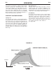
NOMINAL PROCEDURES
The POWER WAVE® is designed to operate with
3/4"(19.1mm) electrode stick-out for CV and Pulse
processes.
FRINGE PROCEDURES
Excessively short or long electrode stick-outs may
function only on a limited basis, if at all.
MAKING A WELD
The serviceability of a product or structure utiliz-
ing the welding programs is and must be the sole
responsibility of the builder/user. Many variables
beyond the control of The Lincoln Electric
Company affect the results obtained in applying
these programs. These variables include, but are
not limited to, welding procedure, plate chemistry
and temperature, weldment design, fabrication
methods and service requirements. The available
range of a welding program may not be suitable
for all applications, and the build/user is and must
be solely responsible for welding program selec-
tion.
------------------------------------------------------------------------
The steps for operating the POWER WAVE® will vary
depending upon the options installed in the user inter-
face (control box) of the welding system. The flexibility
of the POWER WAVE® system lets the user cus-
tomize operation for the best performance.
First, consider the desired welding process and the
part to be welded. Choose an electrode material,
diameter, shielding gas and process (GMAW, GMAW-
P, etc.)
Second, find the program in the welding software that
best matches the desired welding process. The stan-
dard software shipped with the POWER WAVE®s
encompasses a wide range of common processes
and will meet most needs. If a special welding pro-
gram is desired, contact the local Lincoln Electric
sales representative.
To make a weld, the POWER WAVE® needs to know
the desired welding parameters. The Power Feed
(PF) family of feeders communicate settings to the
POWER WAVE® through control cable connection.
Arc length, wire feed speed, arc control, etc. are all
communicated digitally via the control cable.
WARNING