
Manual


Section 5: Torch Consumables and Cutting Charts Spirit II User’s Manual
This information is subject to the controls of the Export Administration Regulations [EAR]. This information shall not be provided to
non-U.S. persons or transferred by any means to any location outside the United States contrary to the requirements of the EAR.
5-30
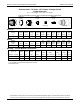
Stainless Steel - 260 Amps - H17 Plasma / Nitrogen Shield
Copper Electrode
(H17 = 17.5% Hydrogen / 32.5% Argon / 50% Nitrogen)
This gas combination gives the best cut quality and minimum dross levels
Shield Cap Nozzle Electrode
277211
277118
277135
Outer Cap
Retaining Cap
Swirl Ring
Torch Head
284150
277280
277139
279100
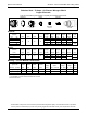
Imperial*
Material
Thickness
Preflow Plasma Shield Postflow
Arc
Voltage
Travel
Speed
Cutting
Height
Pierce
Height
Pierce
Time
Kerf
Width
(in) (psi) (psi) (psi) (psi) (volts) (ipm) (in) (in) (msec) (in)
3/8
40 63 64 63
145 85 .160 .250 500
.190
1/2 142 80 .140 .300 600
5/8 145 65 .185 .350 800
.195
3/4 150 55 .225 .400 1200
1.0 160 33 .250 .450
1500
.200
1.25 *** 170 26 .280 .350 .205
Metric*
Material
Thickness
Preflow Plasma Shield Postflow
Arc
Voltage
Travel
Speed
Cutting
Height
Pierce
Height
Pierce
Time
Kerf
Width
(mm) (psi) (psi) (psi) (psi) (volts) (mm/m) (mm) (mm) (msec) (mm)
10
40 63 64 63
144 2140 4.0 6.5
600 4.8
12 142 2060 3.7 7.3
16 145 1640 4.7 8.9 800
5.0
20 151 1315 5.8 10.3
1500
25 159 875 6.3 11.3 5.1
32 *** 170 650 7.1 8.7 5.2
Marking* – For All Material Thicknesses
Type of Gas Preflow Plasma Shield Postflow
Arc
Voltage
Travel
Speed
Marking
Height
Initial
Height
Pierce
Time
(Plasma) (Shield) (psi) (psi) (psi) (psi) (volts) (ipm) (mm/min) (in) (mm) (in) (mm)
(msec)
Nitrogen Nitrogen N/A 25 25 N/A 108 250 6350 .100 2.5 .100 2.5 0
Argon** Nitrogen**
N/A 50 25 N/A 75 100 2540 .160 4.1 .100 2.5 0
* Use an arc transfer height (ignition height) of .250” (6.4 mm) for cutting and .100” (2.5 mm) for marking.
** Only available on systems with the Automatic Gas Console.
*** Edge start recommended.
(Revised 04/26/2013)