
Manual


Section 5: Torch Consumables and Cutting Charts Spirit II User’s Manual
This information is subject to the controls of the Export Administration Regulations [EAR]. This information shall not be provided to
non-U.S. persons or transferred by any means to any location outside the United States contrary to the requirements of the EAR.
5-38
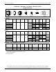
Aluminum - 275 Amps - Air Plasma / Nitrogen Shield
Copper Electrode
Shield Cap Nozzle Electrode
277263
277276
277270
Outer Cap
Retaining Cap
Swi
r
l Ring
Torch Head
284150
277266
277258
279100
Imperial*
Material
Thickness
Preflow Plasma Shield Postflow
Arc
Voltage
Travel
Speed
Cutting
Height
Pierce
Height
Pierce
Time
Kerf
Width
(in) (psi) (psi) (psi) (psi) (volts) (ipm) (in) (in) (msec) (in)
3/8
20 73 65 75
160 160 .160 .275 400
.160
1/2 165 125 .180 .300 500
5/8 168 105 .190 .350 600
.165
3/4 172 85 .200
.400
800
1.00 *** 180 60 .240
1000
.170
1.25 *** 185 45 .260
1.50 *** 190 25 .270 .180
Metric*
Material
Thickness
Preflow Plasma Shield Postflow
Arc
Voltage
Travel
Speed
Cutting
Height
Pierce
Height
Pierce
Time
Kerf
Width
(mm) (psi) (psi) (psi) (psi) (volts) (mm/m) (mm) (mm) (msec) (mm)
10
20 73 65 75
160 3930 4.1 7.1
500 4.1
12 163 3375 4.4 7.4
16 168 2645 4.8 8.9
800 4.2
20 173 2055 5.3
10.2
25 *** 179 1565 6.0
1000
4.3
32 *** 185 1120 6.6
38 *** 189 645 6.8 4.6
Marking* – For All Material Thicknesses
Type of Gas Preflow Plasma Shield Postflow
Arc
Voltage
Travel
Speed
Marking
Height
Initial
Height
Pierce
Time
(Plasma) (Shield) (psi) (psi) (psi) (psi) (volts) (ipm) (mm/min) (in) (mm) (in) (mm)
(msec)
Nitrogen Nitrogen N/A 25 25 N/A 108 250 6350 .100 2.5 .100 2.5 0
Argon** Air** N/A 50 25 N/A 56 100 2540 .120 3.0 .100 2.5 0
* Use an arc transfer height (ignition height) of .275” (7.0 mm) for cutting and .100” (2.5 mm) for marking.
** Only available on systems with the Automatic Gas Console.
*** Edge start recommended.
(Revised 04/26/2013)