
Use and Care Manual


78
www.lincolnelectric.com
GMAW
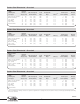
STT II Welding Guidelines
The ensuing procedure guidelines are intended to provide a
starting point for the development of welding procedures using
the STT II power source and STT 10 wire drive and control. The
use of pre-flow, post-flow, and run-in speed are variables that
are established based upon the needs of the application.
Vertical down fillets are set at the suggested guideline setting,
b
ut require an additional 30% to the travel speed.
Diameter, Wires
CTWD Material
Shielding Gas Thickness Wire Feed Speed Peak Background Travel Speed Average
Joint Types Gauge (mm) in/min (M/min.) Amps Amps Tailout
(1)
in/min (M/min.) Current
0.030” (0.8 mm), ER70S-3, 10 3.2 250 (6.4) 250 75 0 - 3 10 (0.3) 110
ER70S-4, ER70S-6 12 2.4 240 (6.1) 245 70 0 - 3 10 (0.3) 107
3/8” (9 mm) 14 2.0 225 (5.7) 245 70 0 - 3 12 (0.3) 105
80% Ar + 20 %CO
2
16 1.6 180 (4.6) 225 60 0 - 3 13 (0.3) 85
Lap, T-Joints, 18 1.1 160 (4.1) 215 55 0 - 3 14 (0.4) 75
Horizontal Fillets 20 0.9 135 (3.4) 200 50 0 - 3 15 (0.4) 65
Carbon Steel Sheetmetal - Uncoated
Diameter, Wires
CTWD Material
Shielding Gas Thickness Wire Feed Speed Peak Background Travel Speed Average
Joint Types Gauge (mm) in/min (M/min.) Amps Amps Tailout
(1)
in/min (M/min.) Current
0.035” (0.9 mm), ER70S-3, 7 5.0 245 (6.2) 340 90 0 - 5 8 (0.2) 150
ER70S-4, ER70S-6 10 3.2 230 (5.8) 330 90 0 - 5 10 (0.3) 145
3/8” (9 mm) 12 2.4 200 (5.1) 320 80 0 - 5 12 (0.3) 135
80%Ar + 20%CO
2
14 2.0 190 (4.8) 300 75 0 - 5 13 (0.3) 125
Lap, T-Joints, 16 1.6 150 (3.8) 260 50 0 - 5 14 (0.4) 95
Horizontal Fillets 18 1.1 125 (3.2) 250 45 0 - 5 15 (0.4) 80
20 0.9 100 (2.5) 220 40 0 - 5 15 (0.4) 65
Carbon Steel Sheetmetal - Uncoated
Diameter, Wires
CTWD Material
Shielding Gas
Thickness Wire Feed Speed Peak Background Travel Speed Average
Joint Types Gauge (mm) in/min (M/min.) Amps Amps Tailout
(1)
in/min (M/min.) Current
0.035” (0.9 mm), ER70S-3, 7 5.0 205 (5.2) 310 85 0 - 6 12 (0.3) 125
ER70S-4, ER70S-6 10 3.2 175 (4.4) 300 75 0 - 6 10 (0.3) 110
3/8” (9 mm)
12 2.4 145 (3.7) 265 60 0 - 7 12 (0.3) 90
54%He + 38%Ar + 8%CO
2
14 2.0 130 (3.3) 240 55 0 - 8 12 (0.3) 85
Lap, T-Joints, 16 1.6 120 (3.0) 235 50 0 - 8 11 (0.3) 75
Horizontal Fillets 18 1.1 110 (2.9) 230 45 0 - 8 12 (0.3) 65
20 0.9 100 (2.5) 225 40 0 - 8 15 (0.4) 55
Carbon Steel Sheetmetal - Uncoated
(1)
Tail-out is adjusted according to end-user acceptance requirements. Increasing tail-out can result in an increase in travel speed and improved wetting
at the toes of a weld.
Background Current controls penetration and is responsible for
t
he overall heat input of the weld.
Peak Current provides arc length – a shorter arc length is
r
equired for higher travel speeds. The peak current also provides
preheat and melts the surface of the base material prior to a
return to background current.
Tail-out Current is applied to add energy to the molten droplet.
Adding tail-out may result in faster travel speeds and improved
toe wetting.
STT
®
II Welding Guidelines