RETURN TO MAIN MENU IM860 IDEALARC ® CV-305 February, 2006 For use with machine Code Numbers 11177, 11178 Safety Depends on You Lincoln arc welding and cutting equipment is designed and built with safety in mind. However, your overall safety can be increased by proper installation ... and thoughtful operation on your part. DO NOT INSTALL, OPERATE OR REPAIR THIS EQUIPMENT WITHOUT READING THIS MANUAL AND THE SAFETY PRECAUTIONS CONTAINED THROUGHOUT.
i i SAFETY WARNING CALIFORNIA PROPOSITION 65 WARNINGS Diesel engine exhaust and some of its constituents are known to the State of California to cause cancer, birth defects, and other reproductive harm. The Above For Diesel Engines The engine exhaust from this product contains chemicals known to the State of California to cause cancer, birth defects, or other reproductive harm. The Above For Gasoline Engines ARC WELDING CAN BE HAZARDOUS.
ii ii SAFETY ELECTRIC SHOCK can kill. 3.a. The electrode and work (or ground) circuits are electrically “hot” when the welder is on. Do not touch these “hot” parts with your bare skin or wet clothing. Wear dry, hole-free gloves to insulate hands. 3.b. Insulate yourself from work and ground using dry insulation. Make certain the insulation is large enough to cover your full area of physical contact with work and ground.
iii iii SAFETY WELDING SPARKS can cause fire or explosion. 6.a. Remove fire hazards from the welding area. If this is not possible, cover them to prevent the welding sparks from starting a fire. Remember that welding sparks and hot materials from welding can easily go through small cracks and openings to adjacent areas. Avoid welding near hydraulic lines. Have a fire extinguisher readily available. 6.b.
SAFETY iv PRÉCAUTIONS DE SÛRETÉ Pour votre propre protection lire et observer toutes les instructions et les précautions de sûreté specifiques qui parraissent dans ce manuel aussi bien que les précautions de sûreté générales suivantes: Sûreté Pour Soudage A L’Arc 1. Protegez-vous contre la secousse électrique: a. Les circuits à l’électrode et à la piéce sont sous tension quand la machine à souder est en marche.
v v Thank You for selecting a QUALITY product by Lincoln Electric. We want you to take pride in operating this Lincoln Electric Company product ••• as much pride as we have in bringing this product to you! Please Examine Carton and Equipment For Damage Immediately When this equipment is shipped, title passes to the purchaser upon receipt by the carrier.
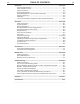
vi TABLE OF CONTENTS Page Installation .......................................................................................................Section A Technical Specifications ........................................................................................A-1 Select Suitable Location ........................................................................................A-2 Input Connections..................................................................................................
INSTALLATION A-1 A-1 TECHNICAL SPECIFICATIONS – IDEALARC CV-305 INPUT - THREE PHASE ONLY Voltage, 60Hz Current at Rated Output, 100% Duty Cycle Code Number 208/230/460 Volts 51/48/24 Amps 11177 230/460/575 Volts 48/24/20 Amps 11178 RATED OUTPUT Duty Cycle Amps Volts at Rated Amperes 100% Duty Cycle NEMA Class I (100) 315 32.
A-2 A-2 INSTALLATION Read entire installation section before starting installation. INPUT CONNECTIONS SAFETY PRECAUTIONS Be sure the voltage, phase, and frequency of the input power is as specified on the welder nameplate. WARNING ELECTRIC SHOCK can kill. • Only qualified personnel should perform this installation. • Turn the input power OFF at the disconnect switch or fuse box before working on this equipment.
A-3 A-3 INSTALLATION LN-742 to CV-305 FIELD INSTALLED OPTIONS a) Turn the CV-305 Power switch to the "OFF" position. For installation of compatible field installed options (see the ACCESSORIES section of this manual and refer to the instructions included with those options. b) Connect the LN-742 control cable to the wire feeder receptacle on the CV-305. REQUIRED EQUIPMENT-CONTROL CABLE CONNECTIONS Follow the instructions below which are appropriate for the wire feeder that will be used.
A-4 INSTALLATION PARALLELING The CV-305 is not designed to be paralleled with itself or any other power source. CONNECTION OF AUXILIARY EQUIPMENT TO THE WIRE FEEDER RECEPTACLE Occasionally, it may be necessary to make connection to the circuits present in the 14-pin wire feeder receptacle. These circuits, such as the auxiliary voltage, contactor, and remote control circuits, may be accessed with a K867 Universal Adapter.
B-1 OPERATION OPERATING INSTRUCTIONS Read and understand this entire section before operating the machine. GENERAL WARNINGS SAFETY PRECAUTIONS WARNING ELECTRIC SHOCK can kill. • Do not touch electrically live parts or electrode with skin or wet clothing. • Insulate yourself from work and ground. • Always wear dry insulating gloves. FUMES AND GASES can be dangerous. • Keep your head out of fumes. • Use ventilation or exhaust to remove fumes from breathing zone.
B-2 B-2 OPERATION GRAPHIC SYMBOLS THAT APPEAR ON THIS MACHINE OR IN THIS MANUAL THERMAL PROTECTION INDICATOR LIGHT OFF ON CIRCUIT BREAKER AC POWER CLOCKWISE ROTATION INCREASES VOLTAGE LOCAL OUTPUT VOLTAGE CONTROL REMOTE OUTPUT VOLTAGE CONTROL WARNING INDICATES WARNING INFORMATION LOCATED ON RIGHT CASE SIDE CV-305
B-3 OPERATION B-3 • 115 VAC, 5 amp auxiliary power available for the wire feeder; circuit breaker protected. CAUTION When using a CV-305 power source with wire feeders, there will be a small spark if the electrode contacts the work or ground within several seconds after releasing the trigger. When used with some wire feeders with the electrical trigger interlock in the ON position, the arc might restart if the electrode touches the work or ground during these several seconds.
B-4 B-4 OPERATION CONTROLS AND OUTPUT SETTINGS All operator controls and adjustments are located on the case front of the CV-305. Refer to Figures B.1. FIGURE B.1 - CONTROL AND OUTPUT PANEL 5 3 4 8 1 7 6 2 9 10 13 11 12 1. POWER SWITCH A two-position toggle switch.Controls the input power to the CV-305. 2. VOLTAGE ADJUST Controls the CV-305 output voltage.
B-5 OPERATION 9. WIRE FEEDER VOLTMETER SWITCH B-5 12. HIGH INDUCTANCE NEGATIVE OUTPUT CONNECTION. This switch selects the polarity of the wire feeder voltmeter, if so equipped. When welding electrode positive (MIG, Outershield and some Innershield processes) set the switch to "+". Output connector is a Magnum Twist-Mate™, receptacle. Insert a mating Twist-Mate™ plug, and twist clockwise to secure.
B-6 B-6 OPERATION STARTING THE MACHINE AUXILIARY POWER The power switch at the extreme right side of the control panel energizes the CV-305. 42 volt AC auxiliary power, as required for some wire feeders, is available through the wire feeder receptacle. A 10 amp circuit breaker protects the 42 volt circuit from overloads. ADJUSTING THE OUTPUT VOLTAGE USING THE DIGITAL METER The digital meters in the CV-305 incorporate a voltage preset function.
C-1 ACCESSORIES FACTORY INSTALLED OPTIONS/ACCESSORIES C-1 COMPATIBLE LINCOLN EQUIPMENT The CV-305 is intended for use with the LF-72, LN-7, LN-742, and LN-25 wire feed units. Use the Cables / Kits listed below to make connection easily: There are no factory installed options/accessories on the CV-305.
D-1 MAINTENANCE SAFETY PRECAUTIONS D-1 MACHINE AND CIRCUIT PROTECTION WARNING The CV-305 Control PC Board has built-in diagnostic routines to alert the operator when trouble exists. When a trouble condition occurs, the CV-305 meter will display an error code, in the form "EXX", where "XX" refers to a specific error. See TROUBLESHOOTING section for an explanation of the error codes. ELECTRIC SHOCK can kill. • Only qualified personnel should perform this maintenance.
E-1 TROUBLESHOOTING E-1 HOW TO USE TROUBLESHOOTING GUIDE WARNING Service and Repair should only be performed by Lincoln Electric Factory Trained Personnel. Unauthorized repairs performed on this equipment may result in danger to the technician and machine operator and will invalidate your factory warranty. For your safety and to avoid Electrical Shock, please observe all safety notes and precautions detailed throughout this manual.
E-2 E-2 TROUBLESHOOTING Observe all Safety Guidelines detailed throughout this manual BUILT-IN DIAGNOSTIC ROUTINES AND ERROR CODES The CV-305 Meter PC Board displays error codes when certain trouble conditions exist. The error codes, trouble conditions, and possible remedies are listed below. ERROR CODE E00 TROUBLE REMEDY 1. Output short circuited. 1. Turn power off. Remove short circuit. 2. May be encountered while starting or welding with 1/16" aluminum wire. 2. a) Turn power off to clear error.
E-3 E-3 TROUBLESHOOTING Observe all Safety Guidelines detailed throughout this manual MACHINE TROUBLESHOOTING GUIDE Not all trouble conditions can be recognized by the PC board, and displayed as error codes. The following guide covers most other trouble conditions. PROBLEMS (SYMPTOMS) POSSIBLE CAUSE RECOMMENDED COURSE OF ACTION PROBLEMS Machine has no output. 1. Secondary contactor circuit (2 and 4 wire feeder receptacle) not working. 2. Electrode or work lead loose or broken. 3.
E-4 E-4 TROUBLESHOOTING Observe all Safety Guidelines detailed throughout this manual PROBLEMS (SYMPTOMS) POSSIBLE CAUSE RECOMMENDED COURSE OF ACTION PROBLEMS Thermal Protection Indicator light is on. 1. Thermostat circuit has opened. 2. Faulty Control PC Board. Machine does not have maximum output 1. Faulty Control PC Board. 2. Voltage Adjust potentiometer defective. 3. Voltage Adjust potentiometer leads open. Machine will not shut off. 1. Defective power switch.
E-5 E-5 TROUBLESHOOTING Observe all Safety Guidelines detailed throughout this manual PROBLEMS (SYMPTOMS) POSSIBLE CAUSE RECOMMENDED COURSE OF ACTION PROBLEMS Output Control not functioning on the 1. Local/Remote switch is in machine. the "Remote" position. 2. Faulty Voltage Adjust potentiometer. 3. Leads or connections open in control circuit. 4. Malfunctioning Remote Control. 5. Faulty Control PC board. Poor arc striking with semiautomatic 1. Poor work connection. wire feeders. 2.
E-6 E-6 TROUBLESHOOTING Observe all Safety Guidelines detailed throughout this manual OPTIONS TROUBLESHOOTING GUIDE K857 (or other) Remote Output Control PROBLEMS (SYMPTOMS) POSSIBLE CAUSE RECOMMENDED COURSE OF ACTION PROBLEMS Output control not functioning on Remote Control. 1. Local/Remote switch in wrong position. 2. Faulty Local/Remote switch. 3. Faulty Remote Control potentiometer. 4. Leads or connections open in control circuit. 5. Faulty Control PC board.
E-7 TROUBLESHOOTING Procedure for Replacing PC Boards E-7 PC BOARD TROUBLESHOOTING PROCEDURES WARNING CONTROL PC BOARD ELECTRIC SHOCK can kill. • Have a qualified individual install and service this equipment. • Turn the power source input power off at the disconnect switch before working on this equipment. • Do not touch electrically hot parts.
E-8 TROUBLESHOOTING E-8 OUTPUT VOLTAGE The open circuit voltage of the machine should be 10 to 43 volts. If any other condition exists, refer to the Troubleshooting Guide. FAULT PROTECTION OPERATION The overload protection circuit on the PC Board will cause the CV-305 meter to display "E60". This protection circuit will reset itself automatically. The short circuit protection circuit will cause the meter to display "E00".
CV-305 23 E 1 2 3 F 7 D 4 208V 8 5 9 6 F 6 5 E 7 2 23 3 8 1 3 9 1 2 D 4 230V 7 E 5 8 23 F 6 TO S1 LINE SWITCH { A B C RECONNECT PANEL 1 D 4 230V N.B. { 5 E 7 2 23 3 8 1 D 4 TO S1 LINE SWITCH F 6 460V 1 1 3 10 11 12 3 9 2 8 23 F 6 E 5 1 7 D 4 460V 1 2 F 6 5 E 23 3 8 2 7 1 D 4 575V 1 1 D1 SCR1 D2 SCR2 s 58V O3 BOT.
CV-305 - ELECTRODE CABLE TO WORK N.C. REMOTE CONTROL OPTIONAL K857 N.C. USE OF THE K857 REMOTE CONTROL REQUIRES THE INSTALLATION OF A K864 REMOTE N.B. DIAGRAM SHOWS ELECTRODE POSITIVE. TO CHANGE POLARITY, TURN POWER "OFF", CONTROL ADAPTER TO THE 14 PIN AMPHENOL OF THE POWER SOURCE. LN-7/LN-7GMA WIRE FEEDER S20662 Modified 7/04 K1818-10 INPUT CABLE ASSEMBLY OPTIONAL K864 REMOTE CONTROL ADAPTER 14 PIN AMPHENOL service this machine.
CV-305 - ELECTRODE CABLE TO WORK K867 UNIVERSAL ADAPTER PLUG 14 PIN AMPHENOL 77 76 75 21 32 GND 31 42 41 4 2 SPARE 82 81 service this machine. REVERSE ELECTRODE AND WORK CABLES AT POWER SOURCE. MIN. 10K N.F. NOT PRESENT ON ALL MACHINES N.E. REFER TO POWER SOURCE INSTRUCTION MANUAL FOR MAXIMUM AUXILIARY CURRENT DRAW. K867 TO 4 2 REMOTE OUTPUT CONTROL N.D. FOR WIRE FEEDERS THAT RETURN A SIGNAL FOR WELDING OUTPUT, USE ISOLATION RELAY TO CLOSE LEADS 2 & 4. N.D. N.C.
CV-305 - ELECTRODE CABLE TO WORK K867 UNIVERSAL ADAPTER PLUG 14 PIN AMPHENOL service this machine. 4 21 4 21 N.D. 2 2 75 76 77 75 76 77 GND GREEN 32 32 GND 31 N.C. 31 41 42 81 82 SPARE Only qualified persons should install, use or Before connecting the wire feeder. using the disconnect switch at the fuse box Turn off input power to the Welding Power Source N.D. SPLICE LEADS AND INSULATE. N.C. INSULATE EACH UNUSED LEAD INDIVIDUALLY. N.B. DIAGRAM SHOWS ELECTRODE POSITIVE.
CV-305 + - TO WORK N.D. LN-25 WIRE FEEDER CONTROL ADAPTER OPTIONAL K864 REMOTE REMOTE CONTROL OPTIONAL K857 ELECTRODE CABLE OPTIONAL K484 JUMPER PLUG 14 PIN AMPHENOL service this machine. Only qualified persons should install, use or Before connecting the wire feeder.
CV-305 + - TO WORK N.C. ELECTRODE CABLE WITH K444-1 OPTION LN-25 WIRE FEEDER CONTROL ADAPTER OPTIONAL K864 REMOTE OPTIONAL K484 JUMPER PLUG 14 PIN AMPHENOL service this machine. Only qualified persons should install, use or Before connecting the wire feeder. using the disconnect switch at the fuse box Turn off input power to the Welding Power Source S20663 6-18-93 DIAGRAMS CLEVELAND, OHIO U.S.A. REMOTE CONTROL ADAPTER. SWITCH THE POWER SOURCE "LOCAL/REMOTE" SWITCH TO REMOTE. N.D.
CV-305 - OUTPUT CONTROL OUTPUT CONTROL WORK 42V AC 42V AC 21 41 42 H I K E 76 D 75 OUTPUT CONTROL 4 77 C F TRIGGER CIRCUIT 2 G TRIGGER CIRCUIT LEAD PIN FUNCTION (SEE APPROPRIATE WIRING DIAGRAM) N.D. E=77 AND 14-PIN CABLE PLUG, REAR VIEW CAN KILL SHOCK ELECTRIC service this machine. Only qualified persons should install, use or Power Source before connecting the wire feeder.
TURN THE POWER SWITCH OF THE WELDING POWER SOURCE OFF BEFORE INSTALLING MAY OR MAY NOT BE ISOLATED, INDEPENDENT CIRCUITS INSIDE THE WELDER.
F-9 F-9 DIAGRAMS TWIST-MATE CABLE PLUG INSTALLATION INSTRUCTIONS TWIST-MATE WELDING CABLE PLUG INSTALLATION INSTRUCTIONS TURN THE POWER SWITCH OF THE WELDING POWER SOURCE "OFF" BEFORE INSTALLING PLUGS ON CABLES OR WHEN CONNECTING OR DISCONNECTING PLUGS TO WELDING POWER SOURCE. 1.
OUTPUT CONTACTOR CONTROL 42 V.A.C. SUPPLY 41 115 V.A.C. SUPPLY 31 N.A. 2 32 10 K OHM MAX. 75 76 77 } } } CV-305 RELAY 4 2 N.D. WIRE FEEDER INPUT POWER GND MIN. GND N.B. 10 K OHM MAX. 75 76 77 N.A. POWER SOURCE MUST BE PROPERLY GROUNDED. RELAY COIL MUST BE RATED FOR THE SAME VOLTAGE THAT IS SUPPLIED BY THE WIRE FEEDER. IF THE WIRE FEEDER REQUIRES AN INPUT VOLTAGE OTHER THAN 42 V.A.C., OR 115 V.A.C. ON SOME MACHINES, AN EXTERNAL POWER SUPPLY FOR THAT VOLTAGE MUST BE PROVIDED. N.B.
CV-305 N.A. 17.25 (438) (CENTERED) 19.20 (487) 19.65 (499) 20.05 (509) 1.68 30.95 (786) N.B. 1.38 (35) 6.20 (157) N.A. 21.50 (546) 24.75 (628) (42.7) 3.61 (91) FOUR SLOTS IN BASE FOR MOUNTING WELDER DOWN USING 5/16 SCREWS 12.60 (320) N.B. HANDLE CONFIGURATION ON EARLIER MODELS. N.A. 23.62 (600) 26.00 (660) 41.58 (1056) 1.00 (25.4) .28 (7.0) N.A. 3.90 (99) 11.
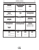
● Do not touch electrically live parts or WARNING Spanish AVISO DE PRECAUCION French ATTENTION German WARNUNG Portuguese ATENÇÃO ● Keep flammable materials away. ● Wear eye, ear and body protection. ● Mantenga el material combustible ● Protéjase los ojos, los oídos y el electrode with skin or wet clothing. ● Insulate yourself from work and ground. ● No toque las partes o los electrodos bajo carga con la piel o ropa mojada. ● Aislese del trabajo y de la tierra.
● Keep your head out of fumes. ● Use ventilation or exhaust to ● Turn power off before servicing. ● Do not operate with panel open or guards off. remove fumes from breathing zone. ● Los humos fuera de la zona de res- piración. ● Mantenga la cabeza fuera de los humos. Utilice ventilación o aspiración para gases. ● Gardez la tête à l’écart des fumées. ● Utilisez un ventilateur ou un aspira- ● Desconectar el cable de ali- mentación de poder de la máquina antes de iniciar cualquier servicio.
• World's Leader in Welding and Cutting Products • • Sales and Service through Subsidiaries and Distributors Worldwide • Cleveland, Ohio 44117-1199 U.S.A. TEL: 216.481.8100 FAX: 216.486.1751 WEB SITE: www.lincolnelectric.