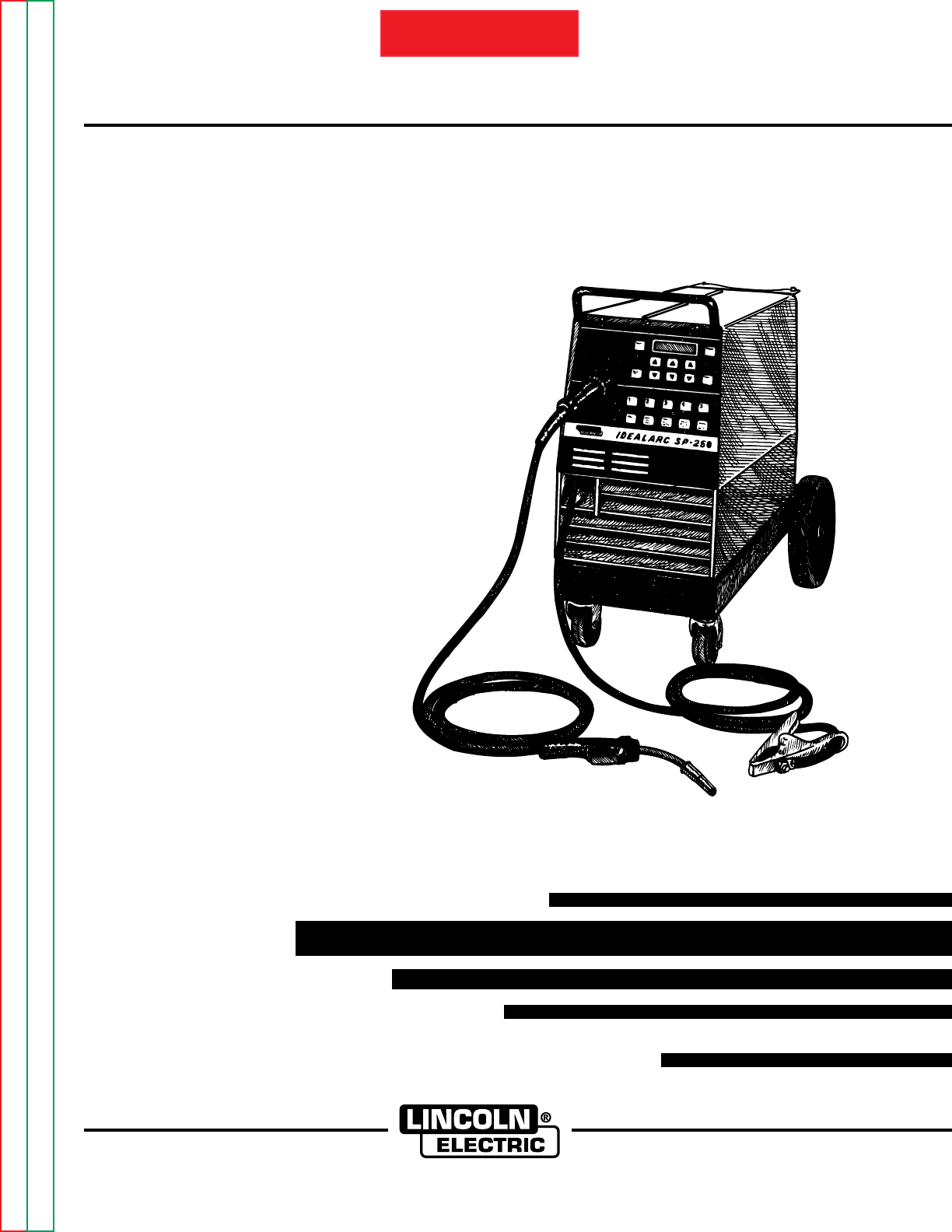
RETURN TO MAIN INDEX View Safety Info Return to Master TOC SVM 111-A IDEALARC SP-250 For use with machines having Code Numbers: January, 1996 9402 9546 9723 10001 10002 Return to Master TOC View Safety Info Return to Master TOC View Safety Info Safety Depends on You Lincoln arc welding and cutting equipment is designed and built with safety in mind. However, your overall safety can be increased by proper installation ... and thoughtful operation on your part.
Return to Master TOC i i SAFETY WARNING ARC WELDING can be hazardous. PROTECT YOURSELF AND OTHERS FROM POSSIBLE SERIOUS INJURY OR DEATH. KEEP CHILDREN AWAY. PACEMAKER WEARERS SHOULD CONSULT WITH THEIR DOCTOR BEFORE OPERATING. Read and understand the following safety highlights. For additional safety information, it is strongly recommended that you purchase a copy of “Safety in Welding & Cutting - ANSI Standard Z49.1” from the American Welding Society, P.O.
Return to Master TOC ii WELDING SPARKS can cause fire or explosion. 4.a. Remove fire hazards from the welding area. If this is not possible, cover them to prevent the welding sparks from starting a fire. Remember that welding sparks and hot materials from welding can easily go through small cracks and openings to adjacent areas. Avoid welding near hydraulic lines. Have a fire extinguisher readily available. 4.b.
Return to Master TOC iii FOR ENGINE powered equipment. 7.a. Turn the engine off before troubleshooting and maintenance work unless the maintenance work requires it to be running. ____________________________________________________ 7.b. Operate engines in open, well-ventilated areas or vent the engine exhaust fumes outdoors. ____________________________________________________ Return to Master TOC iii SAFETY 7.c. Do not add the fuel near an open flame welding arc or when the engine is running.
iv Return to Master TOC Return to Master TOC a. Les circuits à l’électrode et à la piéce sont sous tension quand la machine à souder est en marche. Eviter toujours tout contact entre les parties sous tension et la peau nue ou les vétements mouillés. Porter des gants secs et sans trous pour isoler les mains. b.
v v RETURN TO MAIN INDEX TABLE OF CONTENTS Page Safety . . . . . . . . . . . . . . . . . . . . . . . . . . . . . . . . . . . . . . . . . . . . . . . . . . . . . . .i - v Installation . . . . . . . . . . . . . . . . . . . . . . . . . . . . . . . . . . . . . . . . . Section A Technical Specifications . . . . . . . . . . . . . . . . . . . . . . . . . . . . . . . . . . . . .A-1 Safety Precautions . . . . . . . . . . . . . . . . . . . . . . . . . . . . . . . . . . . . . . . . .A-2 Select Proper Location . .
TABLE OF CONTENTS - INSTALLATION SECTION - INSTALLATION SECTION ........................................ Section A Technical Specifications ...................................................A-1 Safety Precautions ...........................................................A-2 Select Proper Location.....................................................A-2 Stacking.......................................................................A-2 Input Electrical Connections............................................
Return to Master TOC Return to Section TOC A-1 A-1 INSTALLATION TECHNICAL SPECIFICATIONS - Idealarc SP-250 INPUT - SINGLE PHASE/ 60 HERTZ ONLY Standard Voltage Input Current at Rated Output 208/230/1/60 53/49 Amps 230/460/575 50/25/20 Amps Return to Master TOC Return to Section TOC RATED OUTPUT Duty Cycle Amps Volts at Rated Amps 100% 145 amps 26 60% 200 amps 28 35% 250 amps 26 OUTPUT Current Range Maximum Open Circuit Voltage Wire Speed Range 30A - 250A 10V - 40V 50 - 600 IPM
Return to Master TOC Return to Master TOC Return to Section TOC Return to Section TOC A-2 INSTALLATION Read entire Installation Section before installing the IDEALARC SP-250 SAFETY PRECAUTIONS ELECTRIC SHOCK CAN KILL. WARNING • Only qualified personnel should install this machine. • Turn the input power OFF at the disconnect switch or fuse box before working on the equipment. • Do not touch electrically hot parts.
Return to Master TOC Return to Section TOC A-3 INSTALLATION proper grounding of the welder frame when the welder plug is inserted into the receptacle. FUSE AND WIRE SIZES Protect the input circuit with the super lag fuses or delay type circuit breakers listed on the Specifications page of this manual for the machine being used. The tripping action of delay type circuit breakers decreases as the magnitude of the current increases. They are also called inverse time or thermal/magnetic circuit breakers.
Return to Master TOC Return to Section TOC A-4 INSTALLATION For the 230/460/575V/ 60 HZ model which is not equipped with a plug, an input cord, or a receptacle, the input power supply leads are connected directly to the Reconnect Panel as shown Figure A.3. Refer to the specifications table at the beginning of this chapter for proper wiring sizes. b. Strip fi" (13mm) of insulation from the input power supply leads. Return to Master TOC 1. Set the gas cylinder on the rear platform of the SP 250. 2.
Return to Master TOC Return to Section TOC A-5 11. Before opening the cylinder valve, turn the regulator adjusting knob counter clockwise until the pressure is released from the adjusting spring. 12. Open the cylinder valve slowly a fraction of a turn. a. When the cylinder pressure gage pointer stops moving, open the valve fully. Return to Master TOC NEVER STAND DIRECTLY IN FRONT OF OR BEHIND THE FLOW REGULATOR WHEN OPENING THE CYLINDER VALVE. ALWAYS STAND TO ONE SIDE.
Return to Section TOC Return to Master TOC Return to Section TOC Return to Master TOC A-6 INSTALLATION A-6 ALL MACHINES ARE SHIPPED FROM THE FACTORY CONNECTED FOR THE HIGHER OF THE TWO INPUT VOLTAGES LISTED ON THE NAMEPLATE. TO CHANGE VOLTAGE CONNECTION PROCEED AS FOLLOWS: 1. REMOVE THE OUTER STEEL HEX NUT FROM THE TERMINAL WHERE THE TRANSFORMER INPUT LEAD IS CONNECTED. 2.
Return to Master TOC Return to Section TOC A-7 A-7 INSTALLATION CONNECT OUTPUT COMPONENTS GUN LINER & CONTACT TIP INSTALLATION INSTALL THE WORK CLAMP Attach the work clamp to the cable which extends from the front of the machine using the following procedure: The Magnum 250 SP gun and cable provided with the SP-250 is factory installed with a liner for a .035” or .045” (0.9 or 1.2mm) diameter electrode and an .035 (0.9mm) contact tip. 1.
Return to Master TOC Return to Section TOC A-8 GUN & CABLE INSTALLATION WARNING CAUTION WARNING: TURN THE WELDER POWER SWITCH OFF BEFORE INSTALLING GUN AND CABLE. ____________________________________ 1. Lay the cable out straight. Return to Section TOC Return to Master TOC Return to Section TOC Return to Master TOC 2.
TABLE OF CONTENTS - OPERATION SECTION - OPERATION SECTION ............................................ Section B Safety Instructions............................................................B-1 General Description..........................................................B-1 Recommended Processes and Equipment......................B-2 Operational Features and Controls ..................................B-2 Design Features and Advantages ...........................B-3 - B-4 Machine Capability ..............
Return to Master TOC Return to Section TOC B-1 OPERATION Read and understand this entire section before operating your Idealarc SP-250. SAFETY INSTRUCTIONS • automatically computes the proper wire feed speed and arc voltage relationship for the process. ELECTRIC SHOCK can kill. • selects the right procedure for optimum starting, welding, and burnback. Return to Master TOC • Insulate yourself from the work and ground. Return to Section TOC Proper welding setup is simple.
Return to Master TOC Return to Master TOC Return to Section TOC Return to Section TOC B-2 The system includes the following features: • 2-step or 4-step selectable trigger function (above code 9500 only). • both timed spot and stitch welding selections. • drop-in 2" (51mm) O.D. wire reel spindle with a 2230 lb. (10 - 13.6 kg) Readi-Reel- adapter. • integral gas cylinder mounting undercarriage. • 12.5 ft. (3.8m) Magnum 250SP GMAW gun and cable. • dual groove drive roll and a gun liner for .
Return to Master TOC Return to Master TOC Return to Section TOC Return to Section TOC B-3 OPERATION B-3 Automatic Burnback - Provides proper burnback of the electrode to prevent it from sticking in the weld puddle at the end of a weld. Output Terminals - Easily accessible in wire drive section for quick cable connection and polarity reversal.
Return to Master TOC Return to Section TOC B-4 OPERATION Gun and Cable (K524-1) - A 12.5 ft. (3.8) GMAW gun and cable assembly, rated 200 amps 60% duty, is provided with the SP-250 and includes a liner, diffuser, and contact tips for .035 (0.9mm) and .045 (1.2mm) electrodes. The gun is equipped with a Fast-Mate connector with additional control lead connections for the thumb activated 2 momentary position slide switch control designed into the gun handle for use with SP250 remote control features.
Return to Master TOC Return to Master TOC Return to Master TOC Return to Master TOC Return to Section TOC Return to Section TOC Return to Section TOC Return to Section TOC B-5 OPERATION B-5 CONTROLS AND SETTINGS All operator controls are located on the Front Panel Keypad/Nameplate. See Figure B.1 for the location of each control. FIGURE B.1 - SP-250 Control Panel Keys 1. POWER SWITCH: Toggle switch to turn input 3. PROCESS WIRE/GAS KEY: Press key to power ON and OFF.
Return to Master TOC Return to Master TOC ARROW KEY OPERATION WHEN USED WITH PROCESS WIRE/GAS KEY: See Table B.1. Return to Master TOC Left Arrow Keys: Press to set Wire Type. Pressing the UP and DOWN arrow keys changes the Wire Type displayed. Return to Section TOC B-6 OPERATION TABLE B.1 - Arrow Key Functions. Return to Master TOC Return to Section TOC Return to Section TOC Return to Section TOC B-6 Center Arrow Keys: Press to set Wire Diameter.
Return to Master TOC Return to Master TOC Return to Master TOC Return to Section TOC Return to Section TOC Return to Section TOC B-7 OPERATION 4. AUTO KEY: Press for automatic welding set up of recommended Wire Speed and Arc Voltage based on Metal Thickness selected. ARROW KEY OPERATION WHEN USED WITH AUTO KEY: Return to Master TOC ARROW KEY OPERATION WHEN USED WITH MANUAL KEY: See Table B.1. Left arrow keys: Do not function in Manual mode. See Table B.1.
Return to Master TOC Return to Section TOC B-8 OPERATION 7. MEMORY KEYS: Press memory key location number in which you want to save a procedure or from which you want to recall a procedure from memory. See SAVE Key. B-8 Left arrow keys: Do not function. Center arrow keys: Press UP ( ) arrow key to increase Stitch time ON from 0.20 seconds to 2.50 seconds. Press the DOWN ( ) arrow key to decrease Stitch ON time from 2.50 seconds to 0.20 seconds.
Return to Master TOC Return to Master TOC Return to Section TOC Return to Section TOC B-9 B-9 OPERATION 12. TOGGLE KEY: When first pressed, this key turns ON the TOGGLE MODE and recalls the weld setup in memory 4. Pressing the key again switches to the weld setup in memory location 5. Each time the key is pressed, it alternates between the two memory locations.
Return to Master TOC Return to Section TOC B-10 OPERATION OPERATING STEPS Before operating the machine, be sure you have all the materials needed to perform the work. Be sure you are familiar with and have taken all possible safety precautions before starting the work. It is important that you follow these operating steps each time you use the machine. Return to Master TOC Return to Section TOC RUN-IN MODE The IDEALARC SP-250 can operate in either a slow or fast run-in mode.
Return to Master TOC Return to Master TOC Return to Master TOC Return to Section TOC Return to Section TOC Return to Section TOC B-11 OPERATION 10. If SPOT timing mode required. a. Press SPOT key. b. Press CENTER UP or DOWN ARROW keys to select SPOT ON TIME required. c. Press SPOT key to return to previous display. d. Go to Step 12. 11. If STITCH timing mode required. a. Press STITCH key. b. Press CENTER UP and DOWN ARROW keys to select STITCH ON time required. c.
Return to Master TOC Return to Section TOC B-12 OPERATION 4. Press the CENTER UP & DOWN ARROW keys to set the required Spot On time. Suggested initial setting is 1.2 seconds. 5. Press the SPOT key. Display returns to Auto screen. Spot timer status is shown in bottom left corner of screen. 6. Install spot weld nozzle (if available) on gun. Return to Master TOC Return to Section TOC 7. Press spot weld nozzle against the top sheet so the top and bottom sheets are tight together.
Return to Master TOC Return to Section TOC B-13 OPERATION LOADING THE WIRE REEL To mount a 22-30 lb. (10-14 kg) Readi-Reel- package using the Readi-Reel adapter provided: 1. Pull the Readi-Reel adapter and spindle up out of the SP-250 spindle mounting clips (V-brackets). 2. Rotate the spindle and adapter so the retaining spring is at the 12 o'clock position. Return to Master TOC Return to Section TOC 3.
Return to Master TOC Return to Section TOC B-14 OPERATION 2. If the wire "birdnests", jams, or breaks at the drive roll, the idle roll pressure is too great. Back the wing screw out fi turn and run new wire through the gun. Repeat above step. FEEDING ELECTRODE WARNING When inching, the electrode and drive mechanism are always “hot” to work and ground. The electrode remains “hot” several seconds after the gun trigger is released.
TABLE OF CONTENTS - ACCESSORIES SECTION - ACCESSORIES SECTION ....................................... Section C Options/Accessories ........................................................C-1 Replacement Magnum 250-SP Gun and Cable Assemblies........................................................C-1 Spool Gun Adapter Kit Installation Spool Gun Module Board Installation ...................C-1 Spool Gun Connection Box Installation ................C-3 Spool Gun Connection ....................................
Return to Master TOC Return to Master TOC Return to Section TOC Return to Section TOC C-1 OPTIONS / ACCESSORIES Replacement Magnum 250-SP Gun and Cable Assemblies The following GMAW gun and cable assemblies are available for use with the SP-250. Each is rated at 200 amps at 60% duty cycle.
Return to Master TOC CAUTION CAUTION: Collect metal filings with a rag to protect against possible metal contamination of the control board or other internal electrical components. ____________________________________ Figure C.2 - Spool Gun Module Board Installation. 1. Remove input power to the machine before starting. 2. Remove the six screws that hold the Case Side Panels. 3. Locate the four snap-mount fasteners mounted to the side panel of the control Board.
Return to Section TOC Return to Master TOC Return to Section TOC Return to Master TOC C-3 C-3 ACCESSORIES SPOOL GUN CONNECTION BOX INSTALLATION NOTE: Model codes below 9900 require the addition of three holes to the front of the machine's base as shown in Fig C.3. the machine connected for electrode positive, (refer to instruction manual), remove the positive electrode lead from its connection on the wire drive.
Return to Master TOC Return to Section TOC C-4 ACCESSORIES SPOOL GUN CONNECTION CAUTION CAUTION: The spool gun module is intended for use with Lincoln Electric Magnum Spool Guns only. Use with other units may cause damage to the equipment. For Spool Gun operation, refer to the instruction manual provided with the Magnum Spool Gun. Return to Section TOC Return to Master TOC Return to Section TOC Return to Master TOC Return to Section TOC Return to Master TOC 1.
Return to Master TOC Return to Section TOC C-5 ACCESSORIES SPOOL GUN INSTALLATION TO OLD K531 KIT. 1. Slide the spool gun cable assembly through the opening in the louvers provided for the work lead. See Figure C.6. c. Press the MANUAL key for spool gun welding mode. Refer to the Instruction Manual for the K487 or K469 spool gun for information on spool gun set up and operation. 2. Remove the SP-250 gas line from the gas line connector. 3.
TABLE OF CONTENTS - MAINTENANCE SECTION - MAINTENANCE SECTION ...................................... Section D Safety Precautions ...........................................................D-1 Routine and Periodic Maintenance ..................................D-1 Component Locations ......................................................
Return to Master TOC Return to Master TOC Return to Section TOC Return to Section TOC D-1 Drive Rolls and Guide Tubes SAFETY PRECAUTIONS ____________________________________ After every coil of wire, inspect the wire drive mechanism. Clean it as necessary by blowing with low pressure compressed air. Do not use solvents for cleaning the idle roll because it may wash the lubricant out of the bearing. All drive rolls are stamped with the wire sizes they will feed.
Return to Master TOC Return to Section TOC Return to Master TOC Return to Section TOC Return to Master TOC Return to Section TOC Return to Master TOC Return to Section TOC D-2 MAINTENANCE IDEALARC SP-250 D-2 1 2 3 4 5 1 Control Board 4 Choke 2 Fan Assembly 5 Main Transformer 3 SCR Rectifier Figure D.
THEORY OF OPERATION Return to Master TOC TABLE OF CONTENTS - THEORY OF OPERATION SECTION - Return to Master TOC THEORY OF OPERATION SECTION ...................... Section E Power Supply Operation ........................................E-1 - E-3 Input Line Voltage and Main Transformer ...................E-1 Output Rectification and Feedback Control ................E-2 Constant Voltage Output .............................................E-3 Wire Drive Motor and Feedback .................................
E-1 THEORY OF OPERATION POWER SUPPLY OPERATION Return to Master TOC Return to Section TOC E-1 LCD DISPLAY PIEZO ALARM GAS SOLENOID WIRE DRIVE MOTOR KEYPAD CONTROL BOARD TACH MAIN TRANSFORMER Return to Master TOC Return to Section TOC LINE SWITCH G A T E S I G N A L GUN TRIGGER AND THUMB SWITCH FEEDBACK RECONNECT POSITIVE TERMINAL SCR RECTIFIER FAN MOTORS C A P A C I T O R S CHOKE F E E D B A C K NEGATIVE TERMINAL SHUNT Return to Section TOC Return to Master TOC Return to Section TOC
E-2 THEORY OF OPERATION POWER SUPPLY OPERATION (CONTINUED) Return to Master TOC Return to Section TOC E-2 LCD DISPLAY PIEZO ALARM GAS SOLENOID WIRE DRIVE MOTOR KEYPAD CONTROL BOARD TACH MAIN TRANSFORMER Return to Master TOC Return to Section TOC LINE SWITCH G A T E S I G N A L GUN TRIGGER AND THUMB SWITCH FEEDBACK RECONNECT POSITIVE TERMINAL SCR RECTIFIER FAN MOTORS C A P A C I T O R S CHOKE F E E D B A C K NEGATIVE TERMINAL SHUNT Return to Section TOC Return to Master TOC Return to
E-3 THEORY OF OPERATION POWER SUPPLY OPERATION (CONTINUED) Return to Master TOC Return to Section TOC E-3 PIEZO ALARM LCD DISPLAY GAS SOLENOID WIRE DRIVE MOTOR KEYPAD CONTROL BOARD TACH MAIN TRANSFORMER Return to Master TOC LINE SWITCH Return to Section TOC G A T E S I G N A L GUN TRIGGER AND THUMB SWITCH FEEDBACK RECONNECT POSITIVE TERMINAL SCR RECTIFIER FAN MOTORS C A P A C I T O R S CHOKE F E E D B A C K SHUNT Return to Section TOC Return to Master TOC Return to Section TOC Return
E-4 THEORY OF OPERATION POWER SUPPLY OPERATION (CONTINUED) Return to Master TOC Return to Section TOC E-4 LCD DISPLAY PIEZO ALARM GAS SOLENOID WIRE DRIVE MOTOR KEYPAD CONTROL BOARD TACH MAIN TRANSFORMER Return to Master TOC Return to Section TOC LINE SWITCH G A T E S I G N A L GUN TRIGGER AND THUMB SWITCH FEEDBACK RECONNECT POSITIVE TERMINAL SCR RECTIFIER FAN MOTORS C A P A C I T O R S CHOKE F E E D B A C K NEGATIVE TERMINAL SHUNT Return to Section TOC Return to Master TOC Return to
Return to Master TOC Return to Master TOC Return to Master TOC Return to Master TOC Return to Section TOC Return to Section TOC Return to Section TOC Return to Section TOC E-5 THEORY OF OPERATION THERMAL PROTECTION A thermostat protects the machine from excessive operating temperatures.. Excessive operating temperatures may be caused by a lack of cooling air or operating the machine beyond the duty cycle and output rating. There are three thermostats within the SP-250 machine.
E-6 THEORY OF OPERATION SCR OPERATION Return to Master TOC Return to Section TOC E-6 INPUT Return to Master TOC Return to Section TOC CATHODE OUTPUT NOTE: AS THE GATE PULSE IS APPLIED LATER IN THE CYCLE THE SCR OUTPUT IS DECREASED. ANODE GATE Return to Master TOC Return to Master TOC Return to Section TOC Return to Section TOC Figure E.6 - SCR Operation A silicon controlled rectifier (SCR) is a three terminal device used to control rather large currents to a load.
TABLE OF CONTENTS - TROUBLESHOOTING & REPAIR SECTION - TROUBLESHOOTING & REPAIR SECTION ........... Section F How to use Troubleshooting Guide ..................................F-1 PC Board Troubleshooting Procedures............................F-2 Troubleshooting Guide............................................F-3 - F10 Explanation of Prompting Error Messages ............F11 -F-13 Test Procedures SP-250 Main Transformer Test............................F-14 - F-18 Static SCR Rectifier Test ................
Return to Master TOC Return to Section TOC F-1 TROUBLESHOOTING & REPAIR F-1 HOW TO USE TROUBLESHOOTING GUIDE WARNING Return to Master TOC Return to Master TOC Return to Section TOC Return to Section TOC Service and Repair should only be performed by Lincoln Electric Factory Trained Personnel. Unauthorized repairs performed on this equipment may result in danger to the technician and machine operator and will invalidate your factory warranty.
Return to Master TOC Return to Master TOC Return to Master TOC TROUBLESHOOTING & REPAIR F-2 PC BOARD TROUBLESHOOTING PROCEDURES WARNING ELECTRIC SHOCK can kill. Have an electrician install and service this equipment. Turn the input power OFF at the fuse box before working on equipment. Do not touch electrically hot parts. CAUTION: Sometimes machine failures appear to be due to PC board failures. These problems can sometimes be traced to poor electrical connections.
Return to Master TOC Return to Master TOC Return to Section TOC Return to Section TOC F-3 F-3 TROUBLESHOOTING & REPAIR TROUBLESHOOTING GUIDE - Observe all Safety Guidelines detailed throughout this manual PROBLEMS (SYMPTOMS) POSSIBLE AREAS OF MISADJUSTMENTS(S) RECOMMENDED COURSE OF ACTION OUTPUT PROBLEMS Major Physical or Electrical Damage 1. Contact your local Lincoln 1. Contact The Lincoln Electric Service Dept.
Return to Section TOC Return to Master TOC Return to Section TOC Return to Master TOC Return to Section TOC Return to Master TOC Return to Section TOC Return to Master TOC F-4 F-4 TROUBLESHOOTING & REPAIR TROUBLESHOOTING GUIDE - Observe all Safety Guidelines detailed throughout this manual PROBLEMS (SYMPTOMS) POSSIBLE AREAS OF MISADJUSTMENTS(S) RECOMMENDED COURSE OF ACTION OUTPUT PROBLEMS No Open Circuit Voltage output and 1. The thermostats may be open 1.
Return to Master TOC Return to Section TOC F-5 TROUBLESHOOTING & REPAIR F-5 TROUBLESHOOTING GUIDE - Observe all Safety Guidelines detailed throughout this manual PROBLEMS (SYMPTOMS) POSSIBLE AREAS OF MISADJUSTMENTS(S) RECOMMENDED COURSE OF ACTION OUTPUT PROBLEMS The output voltage and wire feed is 1. Remove the gun. If the problem 1. Check the machine's internal trigger leads for grounds or present continuously or pulsing is resolved the gun trigger circuit shorts. See Wiring Diagram.
Return to Master TOC Return to Master TOC Return to Master TOC Return to Master TOC Return to Section TOC Return to Section TOC Return to Section TOC Return to Section TOC F-6 TROUBLESHOOTING & REPAIR F-6 TROUBLESHOOTING GUIDE - Observe all Safety Guidelines detailed throughout this manual PROBLEMS (SYMPTOMS) POSSIBLE AREAS OF MISADJUSTMENTS(S) RECOMMENDED COURSE OF ACTION FUNCTION PROBLEMS The audio alarm does NOT sound 1. The background noise may be 1.
Return to Master TOC Return to Section TOC F-7 TROUBLESHOOTING & REPAIR F-7 TROUBLESHOOTING GUIDE - Observe all Safety Guidelines detailed throughout this manual PROBLEMS (SYMPTOMS) POSSIBLE AREAS OF MISADJUSTMENTS(S) RECOMMENDED COURSE OF ACTION FUNCTION PROBLEMS The display backlight does not func- 1. Check the input voltage at the 1. With the display board disconnected test for 12VDC from pins tion. machine. Input voltage must 1J1(+) to 2J1(-).
Return to Master TOC Return to Master TOC Return to Master TOC Return to Master TOC Return to Section TOC Return to Section TOC Return to Section TOC Return to Section TOC F-8 TROUBLESHOOTING & REPAIR F-8 TROUBLESHOOTING GUIDE - Observe all Safety Guidelines detailed throughout this manual PROBLEMS (SYMPTOMS) POSSIBLE AREAS OF MISADJUSTMENTS(S) RECOMMENDED COURSE OF ACTION WIRE FEEDING PROBLEMS No control of wire feed speed. 1. The thumb switch circuit in the 1.
Return to Section TOC Return to Master TOC Return to Section TOC Return to Master TOC F-9 F-9 TROUBLESHOOTING & REPAIR TROUBLESHOOTING GUIDE - Observe all Safety Guidelines detailed throughout this manual PROBLEMS (SYMPTOMS) POSSIBLE AREAS OF MISADJUSTMENTS(S) RECOMMENDED COURSE OF ACTION WELDING PROBLEMS The arc is unstable and or "hunting". 1. Check for worn or melted con- 1. Check for loose connections at the output terminals, the choke, tact tip.
Return to Master TOC Return to Section TOC F-10 TROUBLESHOOTING & REPAIR F-10 TROUBLESHOOTING GUIDE - Observe all Safety Guidelines detailed throughout this manual PROBLEMS (SYMPTOMS) POSSIBLE AREAS OF MISADJUSTMENTS(S) RECOMMENDED COURSE OF ACTION WELDING PROBLEMS The contact tip seizes in the gas dif- 1. The tip is being over heated due fuser. to excessive high current and /or high duty cycle welding.
Return to Master TOC Return to Master TOC Return to Master TOC Return to Master TOC Return to Section TOC Return to Section TOC Return to Section TOC Return to Section TOC F-11 TROUBLESHOOTING & REPAIR F-11 EXPLANATION OF PROMPTING AND ERROR MESSAGES ON SCREEN ERROR MESSAGE MESSAGE EXPLANATION PROCESS MUST MATCH WIRE & GAS Reminder that in Auto mode the process entered with the Process key must match the process installed in the machine . ONLY SET UP FOR .
Return to Master TOC Return to Section TOC F-12 TROUBLESHOOTING & REPAIR EXPLANATION OF PROMPTING AND ERROR MESSAGES (CONT’D) Return to Section TOC Return to Master TOC Return to Section TOC DATA ***ERROR*** CHECK SETTINGS Return to Master TOC An attempt was made to recall a setup from memory that has improper settings due to excessive electrical interference. The SP-250 will recall the setup and reset the improper data to within machine limits.
Return to Master TOC Return to Section TOC F-13 TROUBLESHOOTING & REPAIR EXPLANATION OF PROMPTING AND ERROR MESSAGES (CONT’D) ON SCREEN ERROR MESSAGE HIGH LINE: CHECK RECONNECT PANEL Return to Master TOC Return to Master TOC Return to Section TOC PRESS ANY KEY TO STOP MESSAGE Return to Section TOC F-13 CURRENT OVERLOAD REDUCE OUTPUT PRESS ANY KEY TO STOP MESSAGE MESSAGE EXPLANATION Indicates to operator that the line voltage is too high, and the output voltage has been reduced to protect the ca
Return to Master TOC Return to Section TOC F-14 TROUBLESHOOTING & REPAIR F-14 MAIN TRANSFORMER TEST WARNING Return to Master TOC Return to Section TOC Service and repair should be performed only by Lincoln Electric factory trained personnel. Unauthorized repairs performed on this equipment could result in danger to the technician or the machine operator and will invalidate your factory warranty.
Return to Master TOC Return to Section TOC F-15 TROUBLESHOOTING & REPAIR MAIN TRANSFORMER TEST TEST PROCEDURE WARNING The ON/OFF POWER SWITCH will be "hot" during these tests. __________________________ NOTE: Secondary voltages will vary proportionably with the primary input voltage. Return to Master TOC Return to Section TOC 1. Disconnect the main input power supply to the machine. 2. Remove the Case Top and Side Panels with a 5/16" nut driver. 3.
Return to Master TOC Return to Section TOC F-16 F-16 TROUBLESHOOTING & REPAIR MAIN TRANSFORMER TEST SP-250 CONTROL G1992 J2 J8 J7 Return to Master TOC Return to Section TOC J4 J9 J6 J5 #208 (1J3) #209 (2J3) #206 (3J3) J3 #204A (5J3) #202 (6J3) Return to Master TOC FIGURE F.1B - G1992 (Code 9402 Only) Control PC Board Main Transformer Test Points. Note: Plugs J5 and J6 are on inboard non-component side of Control Board. 4. Locate the following leads on Plug J3: G1992 (code 9402 only): 5.
Return to Master TOC Return to Master TOC Return to Section TOC Return to Section TOC F-17 TROUBLESHOOTING & REPAIR MAIN TRANSFORMER TEST G1992 (Code 9402 only): G2252: FROM LEAD TO LEAD EXPECTED VOLTAGE FROM LEAD TO LEAD EXPECTED VOLTAGE #202 (6J3) #203 (7J3) 30 VAC #208 (16J6) #209 (7J6) 60 VAC #202 (6J3) #204 A (5J3) 15 VAC #208 (16J6) #206 (4J6) 30 VAC #203 (7J3) #204 A (5J3) 15 VAC #209 (7J6) #206 (4J6) 30 VAC 8. Turn OFF the machine G1992 (Code 9402 only): 9.
Return to Master TOC TROUBLESHOOTING & REPAIR MAIN TRANSFORMER TEST b. If the correct nameplate voltage is being applied to the main transformer and one or more of the secondary voltages are missing or are incorrect, the main transformer may faulty. Replace.
Return to Master TOC Return to Section TOC F-19 TROUBLESHOOTING & REPAIR F-19 STATIC SCR RECTIFIER ASSEMBLY TEST WARNING Return to Master TOC Return to Section TOC Service and repair should be performed only by Lincoln Electric factory trained personnel. Unauthorized repairs performed on this equipment could result in danger to the technician or the machine operator and will invalidate your factory warranty.
Return to Master TOC TROUBLESHOOTING & REPAIR STATIC SCR RECTIFIER ASSEMBLY TEST TEST PROCEDURE 1. Disconnect main AC input power to the machine. 2. Disconnect Plugs J3 and J6 from the G2252 Control Board or remove Plug J3 from the G1992 Control Board (Code 9402 only.) This electrically isolates the SCR bridge assembly. See Figures F.2A and F.2B. J2 J8 LEADS X2 AND X3 J7 J4 J5 Return to Master TOC 4. Disconnect leads X2 and X3 from the negative capacitor bank using a fi" open end wrench.
Return to Section TOC Return to Master TOC Return to Section TOC Return to Master TOC F-21 TROUBLESHOOTING & REPAIR STATIC SCR RECTIFIER ASSEMBLY TEST NOTE: DO NOT DISASSEMBLE THE SCR RECTIFIER HEAT SINK ASSEMBLY. 6. Test for high or infinite resistance from the anode to the cathode of SCR 1. See Figure F.4. Use an analog ohmmeter (Multimeter). Return to Master TOC Return to Section TOC FIGURE F.4 - SCR 1 Test Points. 7.
Return to Master TOC Return to Section TOC F-22 TROUBLESHOOTING & REPAIR F-22 ACTIVE SCR RECTIFIER ASSEMBLY TEST WARNING Return to Master TOC Return to Section TOC Service and repair should be performed only by Lincoln Electric factory trained personnel. Unauthorized repairs performed on this equipment could result in danger to the technician or the machine operator and will invalidate your factory warranty.
Return to Master TOC Return to Section TOC F-23 TROUBLESHOOTING & REPAIR ACTIVE SCR RECTIFIER ASSEMBLY TEST TEST PROCEDURE 1. Disconnect main AC input power to the machine. 2. Disconnect Molex Plugs J3 and J6 from the G2252 Control Board or remove Plug J3 from G1992 Control Board (Code 9402 only) See Figures F.5A and F.5B. 3. Test with an Analog Volt-Ohm meter that capacitors have completely discharged. 4. Disconnect leads X2 and X3 from the negative capacitor bank using a fi" open end wrench.
Return to Master TOC Return to Section TOC F-24 ACTIVE SCR RECTIFIER ASSEMBLY TEST 7. Connect the Tester to the SCR 1 as shown in Figure F.7. a. If the voltage is 3 - 6 volts while the switch is closed and after the switch is open, the SCR is functioning. a. Connect Tester lead (A) to the anode. b. If the voltages is 3-6 volts only when the switch is closed or there is no voltage when the switch is closed, the SCR is defective. b. Connect Tester lead (C) to the cathode. c.
Return to Master TOC Return to Section TOC F-25 TROUBLESHOOTING & REPAIR F-25 SP-250 KEYPAD RESISTANCE TEST WARNING Return to Master TOC Return to Section TOC Service and repair should be performed only by Lincoln Electric factory trained personnel. Unauthorized repairs performed on this equipment could result in danger to the technician or the machine operator and will invalidate your factory warranty.
TROUBLESHOOTING & REPAIR SP-250 KEYPAD RESISTANCE TEST Return to Master TOC Return to Section TOC F-26 TEST PROCEDURE 1. Disconnect main input power to the machine. 4. Measure the resistance of each key at Plug J2 using an analog volt-ohm meter as described in Table F.1. 2. Remove the Case Top and Side Panels using the 5/16" nut driver. a. The resistance measurements are taken from the pin locations on Plug J2. See Figure F.9 for each pin location. J2 J8 J7 J4 J9 J5 J3 J6 FIGURE F.
Return to Master TOC Return to Section TOC F-27 TROUBLESHOOTING & REPAIR SP-250 KEYPAD RESISTANCE TEST TABLE F.1 - SP-250 KEYPAD RESISTANCE TESTS NOTE: THERE SHOULD NOT BE CONTINUITY BETWEEN PINS UNTIL A KEY IS PRESSED ON THE KEYPAD.
Return to Master TOC Return to Section TOC F-28 TROUBLESHOOTING & REPAIR F-28 WIRE DRIVE MOTOR AND TACHOMETER FEEDBACK TEST WARNING Return to Master TOC Return to Section TOC Service and repair should be performed only by Lincoln Electric factory trained personnel. Unauthorized repairs performed on this equipment could result in danger to the technician or the machine operator and will invalidate your factory warranty.
Return to Master TOC Return to Section TOC F-29 TROUBLESHOOTING & REPAIR WIRE DRIVE MOTOR AND TACHOMETER FEEDBACK TEST TEST PROCEDURE NOTE: POLARITY MUST OBSERVED FOR THESE TESTS. BE Test for Correct Wire Drive Motor Armature Voltage 1. Disconnect main input power to the machine. Return to Master TOC Return to Section TOC 2. Remove the Case Top and Side Panels using a 5/16" nut driver. 3. Locate Plug J5 on the G2252 Control Board, or Plug J6 on the G1992 Control Board (Code 9402 only)..
Return to Master TOC Return to Section TOC F-30 F-30 TROUBLESHOOTING & REPAIR WIRE DRIVE MOTOR AND TACHOMETER FEEDBACK TEST J2 Return to Master TOC Return to Section TOC J8 J7 J4 #206B (4J6) #515B (1J6) J5 J9 #555 (2J6) J6 J3 #541 (6J6) Return to Master TOC Return to Section TOC #539 (3J6) FIGURE F.10B - Plug J6 Location on G1992 PC Control Board (Code 9402 only.) NOTE: Plugs J5 and J6 are on the inboard non-component side of the Control Board. 4.
Return to Master TOC Return to Section TOC F-31 TROUBLESHOOTING & REPAIR WIRE DRIVE MOTOR AND TACHOMETER FEEDBACK TEST Test for Supply Tachometer Voltage to 1. Test for 15 VDC between lead #515B (positive) and lead #206B (negative). See Figure F. 10 for pin locations. a. Insert probes into Molex pin cavities. b. If the 1.5 - 3.5 VDC is not present or not correct, the Control Board is not receiving the proper feedback voltage from the tach circuit.
Return to Master TOC Return to Master TOC Return to Master TOC Return to Master TOC Return to Section TOC Return to Section TOC Return to Section TOC Return to Section TOC F-32 TROUBLESHOOTING & REPAIR NORMAL OPEN CIRCUIT VOLTAGE WAVEFORM SCOPE SETTINGS This is a typical DC output voltage waveform generated from a properly operating Volts/Div . . . . . . . . . . . . . . . . .20 V/Div. machine. Note that each vertical division represents 20 volts and that each horizontal Horizontal Sweep . . . . . . .
Return to Section TOC Return to Master TOC Return to Section TOC Return to Master TOC F-33 TROUBLESHOOTING & REPAIR TYPICAL OUTPUT VOLTAGE WAVEFORM - MACHINE LOADED Return to Section TOC Return to Master TOC Return to Section TOC Return to Master TOC MACHINE LOADED TO 250 AMPS AT 26 VDC SCOPE SETTINGS This is a typical DC output voltage waveform generated from a properly operating Volts/Div . . . . . . . . . . . . . . . . .20 V/Div. machine.
Return to Section TOC Return to Master TOC Return to Section TOC Return to Master TOC F-34 TROUBLESHOOTING & REPAIR ABNORMAL OUTPUT VOLTAGE WAVEFORM - MACHINE LOADED ONE OUTPUT SCR NOT FUNCTIONING Return to Master TOC Return to Master TOC Return to Section TOC Return to Section TOC MACHINE LOADED TO 220 AMPS AT 22 VDC SCOPE SETTINGS This is NOT a typical DC output voltage waveform. One output SCR is not functioning. Note the increased ripple content.
Return to Master TOC Return to Master TOC Return to Master TOC Return to Master TOC Return to Section TOC Return to Section TOC Return to Section TOC Return to Section TOC F-35 TROUBLESHOOTING & REPAIR ABNORMAL OPEN CIRCUIT VOLTAGE OUTPUT CAPACITOR BANK NOT FUNCTIONING SCOPE SETTINGS This is NOT the typical DC output voltage waveform. The output capacitors are not Volts/Div . . . . . . . . . . . . . . . . .20 V/Div. functioning. Note the lack of “filtering” in the output waveform.
Return to Master TOC Return to Master TOC Return to Master TOC Return to Section TOC Return to Section TOC Return to Section TOC F-36 TROUBLESHOOTING & REPAIR TYPICAL SCR GATE VOLTAGE WAVEFORM SCOPE SETTINGS This is a typical SCR gate pulse voltage waveform. The machine was in an open cir- Volts/Div . . . . . . . . . . . . . . . . . .2 V/Div. cuit condition (no load) and operating properly. Note that each vertical division repre- Horizontal Sweep . . . . . . . . . .5 ms/Div.
Return to Master TOC Return to Section TOC F-37 CONTROL PC BOARD REMOVAL AND REPLACEMENT CAUTION SP-250 CONTROL G2252 Printed Circuit Boards can be damaged by static electricity. Follow static handling guidelines detailed in “PC Board Troubleshooting Procedures” at the beginning of this chapter.
Return to Section TOC Return to Master TOC Return to Section TOC Return to Master TOC F-38 TROUBLESHOOTING & REPAIR CONTROL PC BOARD REMOVAL AND REPLACEMENT 4. Remove the eight Phillips Head mounting screws using a Phillips Head screwdriver. See Figure F.12. Return to Section TOC Return to Master TOC Return to Section TOC Return to Master TOC FIGURE F.12 - Control Board Mounting Screw Locations may vary with different Code Machines. 5. Lift the Control Board straight up and out from the machine.
Return to Master TOC Return to Section TOC F-39 TROUBLESHOOTING & REPAIR F-39 KEYPAD REMOVAL AND REPLACEMENT WARNING Return to Master TOC Return to Section TOC Service and repair should be performed only by Lincoln Electric factory trained personnel. Unauthorized repairs performed on this equipment could result in danger to the technician or the machine operator and will invalidate your factory warranty.
Return to Master TOC Return to Section TOC F-40 TROUBLESHOOTING & REPAIR KEYPAD REMOVAL AND REPLACEMENT PROCEDURE NOTE: BEFORE REMOVING THE KEYPAD, PERFORM THE KEYPAD RESISTANCE TEST TO BE SURE THE KEYPAD IS FAULTY. 1. Disconnect main input power to the machine. Return to Master TOC Return to Section TOC 2. Remove the Case Top and Side Panels with 5/16" nut driver. 3. Disconnect Keypad Plug J2 from the Control Panel. 4. Remove the two screws holding the POWER SWITCH and bezel using a 1/4" nut driver.
Return to Master TOC Return to Section TOC F-41 TROUBLESHOOTING & REPAIR F-41 WIRE DRIVE ASSEMBLY REMOVAL AND REPLACEMENT WARNING Return to Master TOC Return to Section TOC Service and repair should be performed only by Lincoln Electric factory trained personnel. Unauthorized repairs performed on this equipment could result in danger to the technician or the machine operator and will invalidate your factory warranty.
Return to Master TOC Return to Section TOC F-42 TROUBLESHOOTING & REPAIR WIRE DRIVE ASSEMBLY REMOVAL AND REPLACEMENT PROCEDURE 1. Disconnect main input power to the machine. 2. Remove the Case Top and Side Panels. Return to Section TOC Return to Master TOC Return to Section TOC Return to Master TOC 3. Remove the large mounting screw with a large slot head screwdriver located in front of the drive roll. See Figure F.13. a. Note the placement of the insulators and washers for replacement.
Return to Master TOC Return to Section TOC F-43 TROUBLESHOOTING & REPAIR F-43 SCR OUTPUT RECTIFIER REMOVAL WARNING Return to Master TOC Return to Section TOC Service and repair should be performed only by Lincoln Electric factory trained personnel. Unauthorized repairs performed on this equipment could result in danger to the technician or the machine operator and will invalidate your factory warranty.
Return to Master TOC Return to Section TOC F-44 TROUBLESHOOTING & REPAIR SCR OUTPUT RECTIFIER REMOVAL PROCEDURE 1. Disconnect lead #208 and Transformer Lead X1 from the heat sink on the left side of the machine (facing the front) using a 1/2" socket wrench. See Figure F.14. Return to Master TOC Return to Section TOC a. Thin lead is always on the outboard side of the connection. 4. Cut the SCR gate leads G1 and G2 (see wire markers and wiring diagram) using wire cutters. a.
Return to Master TOC Return to Section TOC F-45 F-45 TROUBLESHOOTING & REPAIR CAPACITOR BANK REMOVAL AND REPLACEMENT WARNING Return to Master TOC Return to Section TOC Service and repair should be performed only by Lincoln Electric factory trained personnel. Unauthorized repairs performed on this equipment could result in danger to the technician or the machine operator and will invalidate your factory warranty.
Return to Section TOC Return to Master TOC Return to Section TOC Return to Master TOC F-46 TROUBLESHOOTING & REPAIR CAPACITOR BANK REMOVAL AND REPLACEMENT PROCEDURE See Figure F.17 for location of Capacitor Bank Removal and Replacement components. Return to Master TOC Return to Master TOC Return to Section TOC Return to Section TOC FIGURE F.17 - Location of Capacitor Bank Removal and Replacement Components 1. Disconnect main input power to the machine. 2.
Return to Master TOC Return to Section TOC F-47 TROUBLESHOOTING & REPAIR F-47 MAIN TRANSFORMER REMOVAL AND REPLACEMENT WARNING Return to Master TOC Return to Section TOC Service and repair should be performed only by Lincoln Electric factory trained personnel. Unauthorized repairs performed on this equipment could result in danger to the technician or the machine operator and will invalidate your factory warranty.
Return to Master TOC Return to Section TOC F-48 TROUBLESHOOTING & REPAIR MAIN TRANSFORMER REMOVAL AND REPLACEMENT 12. Disconnect the positive output lead at the wire drive motor. PROCEDURE 1. Disconnect main input power to the machine. 2. Remove the Case Top and Side Panels. Return to Master TOC Return to Section TOC 3. Perform the Capacitor Removal Procedure. Bank 4. Remove lead X1 from the left side SCR heat sink assembly using a 1/2" socket wrench, extender and universal adapter. 13.
Return to Master TOC Return to Section TOC F-49 TROUBLESHOOTING & REPAIR F-49 FAN MOTOR AND FAN REMOVAL AND REPLACEMENT WARNING Return to Master TOC Return to Section TOC Service and repair should be performed only by Lincoln Electric factory trained personnel. Unauthorized repairs performed on this equipment could result in danger to the technician or the machine operator and will invalidate your factory warranty.
Return to Master TOC Return to Master TOC Return to Master TOC Return to Section TOC Return to Section TOC Return to Section TOC F-50 TROUBLESHOOTING & REPAIR FAN MOTOR AND FAN REMOVAL AND REPLACEMENT PROCEDURE See Figure F.18 for fan motor and fan removal components. FIGURE F.18 - Fan Motor and Fan Removal Components 1. Remove the Case Back screws. Return to Master TOC Return to Section TOC 2. Remove the gas solenoid using a 3/4" open end wrench. 3.
Return to Master TOC Return to Section TOC F-51 TROUBLESHOOTING & REPAIR FAN MOTOR AND FAN REMOVAL AND REPLACEMENT 7. Remove the fan motor. a. Loosen and remove the two screws from the motor mounting bracket using a slot head screw driver. b. When the motor is free from the mounting bracket, place it carefully on the bottom of the machine. Return to Master TOC Return to Section TOC c. Cut any necessary wire wraps bundling the motor leads. d. Remove the leads from the fan motor. 8.
Return to Master TOC Return to Master TOC Return to Section TOC Return to Section TOC F-52 RETEST AFTER REPAIR INPUT IDLE AMPS AND WATTS Input Volts/Hertz Maximum Idle Amps Maximum Idle Watts 230/60 6.4 375 OPEN CIRCUIT VOLTAGE 35-40 VDC Strike Voltage 10 to 40 VDC WIRE SPEED RANGE Return to Section TOC Return to Master TOC Return to Master TOC 50 - 600 IPM (1.27 - 15.
ELECTRICAL DIAGRAMS SECTION ...................... Section G G1992 CONTROL PC BOARD LAYOUT .....................G - 1 G2252 CONTROL PC BOARD LAYOUT ......................G - 5 WIRING DIAGRAM (Code 9402) ..................................G - 9 WIRING DIAGRAM (Code 9546 & 10002)..................G - 10 WIRING DIAGRAM (Code 9723 & 10001) ..................G - 11 G1992 CONTROL PC BOARD SCHEMATIC ............G - 12 G2252 CONTROL PC BOARD SCHEMATIC ............
ELECTRICAL DIAGRAMS G-1 SP-250 CONTROL R129 R130 C85 C86 C87 R131 C11 R132 C88 G1992 CONTROL PC BOARD Return to Master TOC X21 G1992-2 R100 X17 R138 C95 R69 B R97 R67 R106 C27 R54 D53 R61 R3 R111 X6 R4 C47 D69 D38 D72 R12 R121 R77 R15 Q7 R79 R20 C38 X16 R31 C18 C1 DZ7 R45 R43 R22 C19 R23 R47 R118 D76 C14 R46 C2 C50 R83 X11 C56 R37 C55 R36 R35 DD1 R38 R39 X12 R32 R112 R25 Q21 C15 C DZ2 R116 R30 D35 R28 R56 R113 C49 R51 Q9 Q8
Return to Master TOC Return to Master TOC Return to Section TOC Return to Section TOC G-2 ELECTRICAL DIAGRAMS G-2 G1992 CONTROL PC BOARD Item Identification C45 . . . . . . . . . . . . . . .CAPACITOR-PEMF,.047,100V,10% C21 . . . . . . . . . . . . . . . . .CAPACITOR-TAEL,39,20V,10% C16 . . . . . . . . . . . .CAPACITOR-ALEL,2200,63V,+30/-10% C30,C47,C95 . . . . . . . . . .CAPACITOR-TAEL,4.7,35V,10% C15 . . . . . . . . . . . . . . . . .CAPACITOR-TAEL,39,10V,10% C14,C20 . . . . . . . . . . . . . .
Return to Master TOC Return to Section TOC G-3 Item ELECTRICAL DIAGRAMS G-3 G1992 CONTROL PC BOARD 2/95 Identification R16 . . . . . . . . . . . . . . . . . . .RESISTOR-CC,1/2W,10M,5% R32,R54,R119 . . . . . . . . . . . . . .RESISTOR-MF 22K 1/4W R60,R81,R82,R83,R91,R95 . . .RESISTOR-MF 2.2K 1/4W R2,R116 . . . . . . . . . . . . . . . . . .RESISTOR-MF 330 1/4W R61,R107,R108 . . . . . . . . . . . . .RESISTOR-MF 100 1/4W R112 . . . . . . . . . . . . . . . . . . . . .
Return to Section TOC Return to Master TOC Return to Section TOC Return to Master TOC Return to Master TOC Return to Section TOC Return to Master TOC Return to Section TOC G-4 NOTES IDEALARC SP-250 G-4
ELECTRICAL DIAGRAMS G-5 Return to Master TOC G2252 CONTROL PC BOARD SP 250 CONTROL G2252- 16 Return to Section TOC G-5 2 Return to Master TOC Return to Master TOC 9 1 Return to Master TOC Return to Section TOC Return to Section TOC Return to Section TOC 1 NOTE: Lincoln Electric assumes no responsibility for liablilities resulting from board level troubleshooting. PC Board repairs will invalidate your factory warranty.
Return to Master TOC Return to Section TOC G-6 ELECTRICAL DIAGRAMS G2252 CONTROL PC BOARD Item Identification W1 . . . . . . . . . . . . . . . .20 AWG UNINSULATED JUMPER C81 . . . . . . . . . . . . . CAPACITOR-ALEL,50,25V,+75/-10% X10 . . . . . . . . IC-CMOS,INVERTER,SCHMITT,HEX,4584 X16 . . . . . . . . . . . . . . . . . . . . . . .VOLTAGE REGULATOR R48 . . . . . . . . . . . . TRIMMER-MT,1/2W,10K,10%,LINEAR C30,C31 . . . . . . . . . . . CAPACITOR-CEMO,22P,100V,5% C10,C11,C12, . . . . . .
Return to Section TOC Return to Master TOC Return to Section TOC Return to Master TOC G-7 ELECTRICAL DIAGRAMS G-7 G2252 CONTROL PC BOARD Item Identification Item Identification R97,R110,R160,R161, . . . RESISTOR-MF,1/4W,1.50K,1% R171,R172,R188,R189 Q1,Q2,Q3,Q4,Q5, TRANSISTOR-N,T226,0.5A,40V,2N4401 Q10,Q12,Q14,Q22,Q23,Q40,Q41 R23,R115,R147,R187 . . . . RESISTOR-MF,1/4W,15.0K,1% R95 . . . . . . . . . . . . . . . . . RESISTOR-MF,1/4W,16.5K,1% R11,R15,R18,R166,R177 . RESISTOR-MF,1/4W,2.
Return to Section TOC Return to Master TOC Return to Section TOC Return to Master TOC Return to Master TOC Return to Section TOC Return to Master TOC Return to Section TOC G-8 NOTES IDEALARC SP-250 G-8
ELECTRICAL DIAGRAMS Return to Master TOC SP-250 (DUAL VOLTAGE) - WIRING DIAGRAM 4 1 5 2 3 4 2 3 11 MANUAL 12 13 5 6 7 8 (J5) * 5 3 1 1 2 3 4 5 6 541 555 206 6 539 9 5 1 515 4 325 3 327 2 4 324 * 8 SET TOGGLE 4 4 5 7 8 9 10 1 (J12) 2 321 3 324B 6 539B 7 322 8 325B 2 206 3 4 GND 4 5 204A 5 9 202 6 10 203 7 325 8 204S 9 207 10 320 11 541B 1 GENERAL INFORMATION (J3) ELECTRICAL SYMBOLS PER E1537 (J11) COLOR CODE: B - BL
ELECTRICAL DIAGRAMS G-10 Return to Master TOC WIRING DIAGRAM FOR CODE 9546 & 10002 SP-250 (230/460/575V) - WIRING DIAGRAM 2 3 4 (J9) 1 2 3 4 5 6 7 8 495 1 5 6 R 7 B (J1) 8 * 9 2 3 4 5 6 12 GND 13 207 5 GND 6 (J2) * Return to Master TOC 1 7 MEMORY 2 3 5 4 9 (J5) 5 * 6 8 SPOT STITCH SET SET TIMERS DISPLAY OFF IPM VOLTS 4 7 324 8 8 539 9 541 10 9 7 205 12 13 DISPLAY 5 204 6 G2 7 327 13 325A 14 320 15 208 16 * (J3) (J11) 10 11
ELECTRICAL DIAGRAMS G-11 Return to Master TOC WIRING DIAGRAM FOR CODE 9723 & 10001 SP-250 (DUAL VOLTAGE) - WIRING DIAGRAM 1 5 2 3 4 (J9) 1 2 3 4 5 6 7 8 495 4 6 542 324B 2 3 4 543 325B F OPTIONAL SPOOL OR PULL GUN RECEPTACLE R 7 B (J1) 8 * 9 2 3 4 5 6 12 13 2 3 5 4 9 (J5) * 8 STITCH SET SET TIMERS DISPLAY OFF IPM VOLTS 4 207 5 GND 6 6 326 DISPLAY 4 7 7 324 8 8 539 9 9 541 10 205 G1 5 204 6 G2 7 206S 13 325A 14 327 320 15
P4 8 2 325 J3 J4 P4 P3 204S P3 207 TACH 9 10 J3 J3 4 2 1 10K 1N4007 D59 1N4007 D58 D60 D61 1N4007 J6 J6 J6 +15 V D28 +15 V 330 R116 50V 35V 4.7 C95 .33mH L6 .33mH L5 .33mH L4 .33mH C51 0.1 C50 C49 2.2K L3 6.8K R68 D25 1K 2N4123 Q2 D46 5 6 D48 3 2 C X1 B X1 6 6.8K R53 6.8K R105 - D30 1/2W 1.8K 50V 2700p C17 9 4.7K REF 6 7 8 9 10 1/2W 1.
324A P4 J4 207 2 J4 P4 .33mH L7 325 COM 324 TRIG 327 DECR 326 INCR 14 5 28.0K 1N4007 D13 1N4007 D11 1N4007 D9 J2 J2 J2 J2 D1 40V J5 J5 J5 J5 1N4007 50V .27 C64 D76 D73 D71 15 50V 0.1 B X1 C X1 11 40V D6 J6 1 C3 7 5.62K 6.81K 6.81K R133 .