RETURN TO MAIN MENU Operator’s Manual ® RANGER 225 For use with machines having Code Numbers: 11597, 11734, 11790, 11797, 12093, 12199 Register your machine: www.lincolnelectric.com/register Authorized Service and Distributor Locator: www.lincolnelectric.com/locator Need Help? Call 1.888.935.3877 to talk to a Service Representative Hours of Operation: 8:00 AM to 6:00 PM (ET) Mon. thru Fri. Save for future reference Date Purchased After hours? Use “Ask the Experts” at lincolnelectric.
THANK YOU FOR SELECTING A QUALITY PRODUCT BY LINCOLN ELECTRIC. PLEASE EXAMINE CARTON AND EQUIPMENT FOR DAMAGE IMMEDIATELY When this equipment is shipped, title passes to the purchaser upon receipt by the carrier. Consequently, Claims for material damaged in shipment must be made by the purchaser against the transportation company at the time the shipment is received. SAFETY DEPENDS ON YOU Lincoln arc welding and cutting equipment is designed and built with safety in mind.
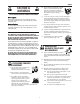
SAFETY 1.d. Keep all equipment safety guards, covers and devices in position and in good repair.Keep hands, hair, clothing and tools away from V-belts, gears, fans and all other moving parts when starting, operating or repairing equipment. SECTION A: WARNINGS CALIFORNIA PROPOSITION 65 WARNINGS 1.e. In some cases it may be necessary to remove safety guards to perform required maintenance. Remove guards only when necessary and replace them when the maintenance requiring their removal is complete.
SAFETY ELECTRIC SHOCK CAN KILL. ARC RAYS CAN BURN. 3.a. The electrode and work (or ground) circuits are electrically “hot” when the welder is on. Do not touch these “hot” parts with your bare skin or wet clothing. Wear dry, hole-free gloves to insulate hands. 4.a. Use a shield with the proper filter and cover plates to protect your eyes from sparks and the rays of the arc when welding or observing open arc welding. Headshield and filter lens should conform to ANSI Z87. I standards. 3.b.
SAFETY WELDING AND CUTTING SPARKS CAN CAUSE FIRE OR EXPLOSION. CYLINDER MAY EXPLODE IF DAMAGED. 7.a. Use only compressed gas cylinders containing the correct shielding gas for the process used and properly operating regulators designed for the gas and pressure used. All hoses, fittings, etc. should be suitable for the application and maintained in good condition. 6.a. Remove fire hazards from the welding area. If this is not possible, cover them to prevent the welding sparks from starting a fire.
vi TABLE OF CONTENTS Page Installation.......................................................................................................................Section A Technical Specifications .......................................................................................................A-1 Safety Precautions ........................................................................................................A-2 Machine Grounding ...................................................................
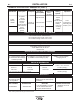
A-1 A-1 INSTALLATION TECHNICAL SPECIFICATIONS - RANGER® 225 ( K2857-1) INPUT - GASOLINE ENGINE Description Make/Model Kohler CH23S, CH680 CH730 Horsepower 2 cylinder 4 Cycle Air-Cooled Gasoline Engine. Aluminum Alloy with Cast Iron Liners, Electronic Ignition Operating Speed (RPM) Displacement cu. in. (cu.cm.) High Idle 3700 23 HP @ 3600 RPM Full Load 3500 41.1(674) Low Idle 2200 44.2(724) Starting System Capacities 12VDC Battery Electric Start Fuel: Group 58 12 Gal (45.
A-2 A-2 INSTALLATION SAFETY PRECAUTIONS WARNING Do not attempt to use this equipment until you have thoroughly read the engine manufacturerʼs manual supplied with your welder. It includes important safety precautions, detailed engine starting, operating and maintenance instructions, and parts lists. -----------------------------------------------------------------------ELECTRIC SHOCK can kill. • Do not touch electrically live parts or electrode with skin or wet clothing.
INSTALLATION A-3 3. Proper placement of the equipment on the trailer to insure stability side to side and front to back when being moved and when standing by itself while being operated or serviced. 4. Typical conditions of use, i.e., travel speed; roughness of surface on which the trailer will be operated; environmental conditions. 5. Conformance with federal, state and local laws(1) A-3 FUEL Fill the fuel tank with clean, fresh, lead-free gasoline.
A-4 A-4 INSTALLATION WELDING OUTPUT CABLES ADDITIONAL SAFETY PRECAUTION With the engine off, connect the electrode and work cables to the studs provided. These connections should be checked periodically and tightened if necessary. Loose connections will result in overheating of the output studs. When welding at a considerable distance from the welder, be sure you use ample size welding cables. Listed below are copper cable sizes recommended for the rated current and duty cycle.
A-5 INSTALLATION A-5 • LOCATION / VENTILATION The welder should be located to provide an unrestricted flow of clean, cool air to the cooling air inlets and to avoid heated air coming out of the welder recirculating back to the cooling air inlet. Also, locate the welder so that engine exhaust fumes are properly vented to an outside area. STACKING RANGER® 225 machines cannot be stacked. CONNECTION OF LINCOLN ELECTRIC WIRE FEEDERS WARNING Shut off welder before making any electrical connections.
A-6 A-6 INSTALLATION WELDER OPERATION 120/240 VOLT DUAL VOLTAGE RECEPTACLE WELDER OUTPUT • Maximum Open Circuit Voltage at 3700 RPM is 80 Volts RMS. • Duty Cycle is the percentage of time the load is being applied in a 10 minute period. For example, a 60% duty cycle represents 6 minutes of load and 4 minutes of no load in a 10 minute period. Duty Cycle for the RANGER® 225 is 100%.
A-7 A-7 INSTALLATION TABLE lll ELECTRICAL DEVICE USE WITH THE RANGER® 225. Type Common Electrical Devices Possible Concerns Resistive Heaters, toasters, incandescent light bulbs, electric range, hot pan, skillet, coffee maker. NONE Capacitive TV sets, radios, microwaves, appliances with electrical control. Voltage spikes or high voltage regulation can cause the capacitative elements to fail.
A-8 INSTALLATION AUXILIARY POWER WHILE WELDING Simultaneous welding and power loads are permitted by following Table I. The permissible currents shown assume that current is being drawn from either the 120V or 240V supply (not both at the same time). Also, the “Output Control” is set at “10” for maximum auxiliary power. TABLE I SIMULTANEOUS WELDING AND POWER Output Selector Setting * Permissible Power Watts (Unity Power Permissible Auxiliary Current in Amperes Factor) @ 120V *-or- @ 240V Max.
A-9 INSTALLATION Figure 1 CONNECTION OF RANGER® 225 TO PREMISES WIRING WARNING Connection of RANGER® 225 to premises wiring must be done by a licensed electrician and must comply with the National Electrical Code and all other applicable electrical codes.
B-1 OPERATION SAFETY PRECAUTIONS Do not attempt to use this equipment until you have thoroughly read the engine manufacturerʼs manual supplied with your welder. It includes important safety precautions, detailed engine starting, operating and maintenance instructions, and parts lists. -----------------------------------------------------------------------ELECTRIC SHOCK can kill. • Do not touch electrically live parts or electrode with skin or wet clothing.
B-2 “ B-2 OPERATION RANGE” SWITCH The “Range” switch is used to select one of four amperage ranges with generous overlap for Stick/TIG welding, or one Wire Feed welding range. Process Range Setting Current Range STICK/TIG (constant current) (3 range settings) 90 Max. 145 Max. 225 MAX 40 to 90 Amps 70 to 145 Amps 120 to 225 Amps WIRE FEED (constant voltage) (1 range setting) 15 to 25V Up to 200 Amps CAUTION Never change the “RANGE” Switch setting while welding. This will damage the switch.
B-3 B-3 OPERATION STARTING/SHUTDOWN INSTRUCTIONS STARTING THE ENGINE STOPPING THE ENGINE Remove all welding and auxiliary power loads and allow engine to run at low idle speed for a few minutes to cool the engine. WARNING • Do not touch electrically live parts of electrode with skin or wet clothing. • Keep flammable material away. • Insulate yourself from work and ground. Wear eye, ear, and body protection. • Keep your head out of the fumes.
B-4 B-4 OPERATION WELDING PROCESS For any electrodes the procedures should be kept within the rating of the machine. For electrode information see the appropriate Lincoln publication. STICK (CONSTANT CURRENT) WELDING Connect welding cables to the "TO WORK” and "ELECTRODE” studs. Start the engine. The “RANGE” switch markings indicate the maximum current for that range as well as the typical electrode size for that range.
B-5 B-5 OPERATION WIRE FEED WELDING PROCESSES (CONSTANT VOLTAGE) ARC GOUGING The Innershield® electrode recommended for use with the RANGER® 225 is NR®-211-MP. The electrode sizes and welding ranges that can be used with the RANGER® 225 are shown in the following table: The RANGER® 225 can be used for limited arc gouging. Diameter (in.) .035 .045 .068 Wire Speed Range In./Min.
C-1 OPTIONAL EQUIPMENT ACCESSORIES (Field Installed) K2635-1 SMALL TWO-WHEEL ROAD TRAILER WITH DUO-HITCH-For heavy-duty road, off-road, plant and yard use. Includes pivoting jack stand, safety chains, and 13" wheels. Overall width 60". Stiff .120" welded rectangular steel tube frame construction is phosphate etched and powder coat painted for superior rust and corrosion resistance. Low sway suspension gives outstanding stability with manageable tongue weight.
C-2 ACCESSORIES C-2 RECOMMENDED EQUIPMENT Optional TIG Equipment: STICK K939-1 Docking Kit - For Mounting the K930-2 TIG Module on top of the RANGER® 225. K704 Accessory Kit- (400 AMP Capacity) which includes: • Electrode Holder & Cable • Work Clamp & Cable • Headshield K937-45 Control Cable Extension - Allows TIG Module to be operated at distances up to 200ft. from the power source. Available in 45ft. (13.7m).
D-1 D-1 MAINTENANCE SAFETY PRECAUTIONS WARNING Have qualified personnel do the maintenance work. Turn the engine off before working inside the machine. In some cases, it may be necessary to remove safety guards to perform required maintenance. Remove guards only when necessary and replace them when the maintenance requiring their removal is complete. Always use the greatest care when working near moving parts. Do not put your hands near the engine cooling blower fan.
D-2 MAINTENANCE Use 4-stroke motor oil that meets or exceeds the requirements for API service classification SG or SH. Always check the API SERVICE label on the oil container to be sure it includes the letters SG or SH. AIR CLEANER AND OTHER MAINTENANCE • Air Cleaner - With normal operating conditions, the maintenance schedule for cleaning and re-oiling the foam pre-filter is every 25 hours and replacement of the air cleaner filter every 100 hours.
D-3 D-3 MAINTENANCE ENGINE ADJUSTMENTS WARNING GASES FROM BATTERY can explode. • Keep sparks, flame and cigarettes away from battery. OVERSPEED IS HAZARDOUS To prevent EXPLOSION when: • INSTALLING A NEW BATTERY - disconnect negative cable from old battery first and connect to new battery last. WARNING The maximum allowable high idle speed for this machine is 3750 RPM, no load. Do NOT tamper with governor components or setting or make any other adjustments to increase the maximum speed.
E-1 TROUBLESHOOTING E-1 HOW TO USE TROUBLESHOOTING GUIDE WARNING Service and Repair should only be performed by Lincoln Electric Factory Trained Personnel. Unauthorized repairs performed on this equipment may result in danger to the technician and machine operator and will invalidate your factory warranty. For your safety and to avoid Electrical Shock, please observe all safety notes and precautions detailed throughout this manual.
E-2 E-2 TROUBLESHOOTING Observe all Safety Guidelines detailed throughout this manual PROBLEMS (SYMPTOMS) No welder output power or Auxiliary Power. POSSIBLE CAUSE RECOMMENDED COURSE OF ACTION 1. Open in miscellaneous leads. 2. Open lead in flashing or field circuit. 3. Faulty rotor. 4. Faulty Potentiometer (R1). 5. Faulty stator Field winding. 6. Faulty Field rectifier (On PCB*). 7. Faulty P.C. Board. Engine will not idle down to low speed. 1. Idler switch on High Idle.
E-3 E-3 TROUBLESHOOTING Observe all Safety Guidelines detailed throughout this manual PROBLEMS (SYMPTOMS) Engine will not go to high idle when using auxiliary power. Engine will not crank or is hard to crank. Engine shuts down. POSSIBLE CAUSE 1. No voltage signal from the current sensor. 2. Auxiliary power load less than 100 to 150 watts. 3. Faulty P.C. Board. 1. Battery will not hold a charge. Faulty Battery. 2. No or insufficient charging current. 3. Loose battery cable connection(s). 1.
NOTE: This diagram is for reference only. It may not be accurate for all machines covered by this manual. The specific diagram for a particular code is pasted inside the machine on one of the enclosure panels. If the diagram is illegible, write to the Service Department for a replacement. Give the equipment code number.
F-2 DIAGRAMS RANGER® 225 F-2
RANGER® 225 42.10 20.80 24.86 21.44 41.20 TRUCK/UNDERCARRIAGE MOUNTING HOLES 2.6 17.50 19.50 14.13 CENTER OF GRAVITY WITH OIL IN ENGINE AND EMPTY FUEL TANK. 10.78 29.88 33.62 36.24 DIMENSION PRINT M22195 A NOTE: CASE FRONT GRAPHICS MAY NOT MATCH ALL CODES. CIRCU CUIT BREAKE AKERS 7.22 10.
RANGER® 225 42.10 1069.46 24.86 631.33 21.38 542.92 20.80 528.28 41.20 1046.48 TRUCK/UNDERCARRIAGE MOUNTING HOLES 2.6 66.55 17.50 19.50 444.5 495.3 15.25 387.35 CIRCUIT BREAKERS 10.78 273.93 29.88 758.95 33.62 853.97 INCH MM 36.24 920.43 NOTE: CASEFRONT GRAPHICS MAY NOT MATCH ALL CODES. CENTER OF GRAVITY WITH OIL IN ENGINE AND EMPTY FUEL TANK. 10.27 260.98 7.22 183.
P-618 P-618 PARTS LIST FOR Ranger® 225 This parts list is provided as an informative guide only. It was accurate at the time of printing. These pages are only updated on the Service Navigator DVD and in Lincoln Electricʼs official Parts Book (BK-34). When ordering parts, always refer to Lincoln Electricʼs official Parts Book (BK-34) for the latest pages.
P-618-A P-618-A ILLUSTRATION OF SUB ASSEMBLIES 7 4 5 6 2 1 3 RANGER® 225 04-23-2013
P-618-A.1 P-618-A.1 Ranger® 225 For Codes: 11597, 11734, 11790, 11797, 12093 & 12199 Do Not use this Parts List for a machine if its code number is not listed. Contact the Service Department for any code numbers not listed. PAGE NO. CODE NO. 1 2 3 4 5 6 7 Control Panel Assembly Base/Fuel Tank/Battery Assembly Engine Assembly Blower Baffle Assembly Stator/Rotor Assembly Covers & Case Back Assembly SUB ASSEMBLY PAGE NAME Miscellaneous Items Sub Assembly Item No.
P-618-B.2 # Indicates a change this printing. ITEM DESCRIPTION Plug & Lead Assembly MISCELLANEOUS ITEMS P-618-B.2 (THESE ITEMS ARE NOT ILLUSTRATED) Use only the parts marked “x” in the column under the heading number called for in the model index page. PART NO. QTY.
NOTES RANGER® 225
P-618-C P-618-C Case Front Assembly 1 22A 23A 23B 13 12 3B 3A 22B 9A 7 8 9B 15A 15B 19C 19B 19A 11 10 5 6A RANGER® 225 04-23-2013
P-618-C.1 P-618-C.1 # Indicates a change this printing. Use only the parts marked “x” in the column under the heading number called for in the model index page. ITEM DESCRIPTION PART NO. QTY.
P-618-D P-618-D Control Panel Assembly 1A 20A 3A 6 5A 12 4A 19A 19B 21A 5B 11 2A 10 RANGER® 225 04-23-2013
P-618-D.1 P-618-D.1 # Indicates a change this printing. Use only the parts marked “x” in the column under the heading number called for in the model index page. ITEM DESCRIPTION PART NO. QTY.
P-618-E P-618-E Base/Fuel Tank/Battery Assembly 4J 4C 4H 10A 4D 4B 4E 4F 4A 11A 13A 11B 7 6C 6A 6D 6E 13B 2A 6B 5A 1 2B 20 22 RANGER® 225 04-23-2013
P-618-E.1 P-618-E.1 # Indicates a change this printing. Use only the parts marked “x” in the column under the heading number called for in the model index page. ITEM DESCRIPTION PART NO. QTY.
P-618-F P-618-F Engine Assembly 1 2 1F 1E 1C 1D 1A 1D 1B RANGER® 225 04-23-2013
P-618-F.1 P-618-F.1 # Indicates a change this printing. Use only the parts marked “x” in the column under the heading number called for in the model index page. ITEM DESCRIPTION PART NO. QTY.
P-618-G P-618-G Blower Baffle Assembly 7B 1A 11 12 7A 3 11 RANGER® 225 04-23-2013
P-618-G.1 P-618-G.1 # Indicates a change this printing. Use only the parts marked “x” in the column under the heading number called for in the model index page. ITEM DESCRIPTION PART NO. QTY.
P-618-H P-618-H Stator/Rotor Assembly 4A 4B 4C 7 1 5B 1A 1F 5A 1D 1E 1C 1B 9 8B 10C 8A 15D 15F 10B 11 10A 15E 15C 15A 15C 15B RANGER® 225 04-23-2013
P-618-H.1 P-618-H.1 # Indicates a change this printing. Use only the parts marked “x” in the column under the heading number called for in the model index page. ITEM DESCRIPTION PART NO. QTY.
P-618-J P-618-J Covers & Case Back Assembly 12B 20 12A 10 11 3A 15 28A 31 17 28B 22 4A 23 30 14 5A 32 18 2A 6B 6A 6F 6C 7 18 1A 16 RANGER® 225 04-23-2013
P-618-J.1 P-618-J.1 # Indicates a change this printing. Use only the parts marked “x” in the column under the heading number called for in the model index page. ITEM DESCRIPTION PART NO. QTY.
NOTES RANGER® 225
NOTES RANGER® 225
WARNING Spanish AVISO DE PRECAUCION French ATTENTION German WARNUNG Portuguese ATENÇÃO • Do not touch electrically live parts or • Keep flammable materials away. • Wear eye, ear and body protection.
• Keep your head out of fumes. • Use ventilation or exhaust to remove • Turn power off before servicing. • Los humos fuera de la zona de res- • Desconectar el cable de alimentación • No operar con panel abierto o fumes from breathing zone. piración. • Mantenga la cabeza fuera de los humos. Utilice ventilación o aspiración para gases. de poder de la máquina antes de iniciar cualquier servicio. • Do not operate with panel open or guards off. guardas quitadas.
CUSTOMER ASSISTANCE POLICY The business of The Lincoln Electric Company is manufacturing and selling high quality welding equipment, consumables, and cutting equipment. Our challenge is to meet the needs of our customers and to exceed their expectations. On occasion, purchasers may ask Lincoln Electric for advice or information about their use of our products. We respond to our customers based on the best information in our possession at that time.