
Manual


A-2
INSTALLATION
X-TRACTOR 2G
A-2
Read this entire installation section before you
start installation.
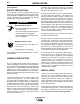
SAFETY PRECAUTIONS
Do not attempt to use this equipment until you have
thoroughly read all installation, operating and mainte-
nance information supplied with your equipment. They
include important safety precautions and detailed
operating and maintenance instructions.
ELECTRIC SHOCK can kill.
• Do not touch electrically live parts such
as internal wiring.
• Turn the input power off at the fuse box
before working on this equipment.
• Have a qualified person install and ser-
vice this equipment.
------------------------------------------------------------------------
MOVING PARTS can injure.
• Do not operate with covers open or fil-
ter removed.
• Keep away from moving parts.
------------------------------------------------------------------------
Only qualified personnel should install, use or service
this equipment.
GENERAL DESCRIPTION
This arc welding smoke exhaust unit will provide the
vacuum needed for two X-Tractor or Flux-Cored Fume
guns, collect visible particles that enter and discharge
the filtered air. This vacuum does not filter out
gases. The X-Tractor 2G retains 2.9 cubic feet of
smoke particles in a removable bin. This is the equiv-
alent of the smoke generated by 2000 pounds of .120
NS-3M electrode.
The smoke is drawn into the cabinet and the filter
traps the smoke particles. The filter consists of 20
envelopes made of polyester sateen. A screen in the
envelope keeps the envelope sides from collapsing as
the filters load up with smoke. The filters are rated 98
to 99.7% efficient at 1 micron particle size and 90 to
98% efficient at .5 micron particle size. These values
apply to a filter that has been loaded several times.
The filter material will release the smoke particles
when the vacuum is off and the filters are bent back
and forth by a shaker bar.
The shaker bar is a simple lever that bends the filter
envelopes when rotated by a handle on the cabinet
side. The shaker bar access hole through the side of
the cabinet is sealed with an "O" ring.
A hinged door provides access to a rectangular stor-
age bin located under the filters. The edges of the
door are lined with rubber to provide a vacuum seal
when the door is closed. The bin has a 2.9 cubic foot
capacity and can be easily removed from the cabinet.
Shed strips attached to the sides of the cabinet above
the bin direct smoke particles into the bin when the fil-
ters are cleaned. Plastic bags made of .004 polyethyl-
ene are used to line the bin. The bags are of special
construction to conform to the rectangular shape of
the bin. The bag is kept in place by draping the edges
of the bag over the sides of the bin.
An integral regenerative type vacuum motor is used to
provide the required vacuum.
Mounting holes are provided on the top of the cabinet
to fit the motor. A two-inch I.D. spring reinforced rub-
ber elbow connects the vacuum motor inlet to the cab-
inet. A muffler is attached to the vacuum motor outlet.
For single gun operation, a stopper is used to plug up
the second inlet. This stopper has an orifice in it to
provide additional air flow through the vacuum motor
so it doesn't overheat and shorten bearing life.
A box mounted on top of the cabinet contains the vac-
uum motor controls. A magnetic starter is used to
connect the motor to the input power. A start and stop
pushbutton is connected to the starter to provide no
voltage release. A 75 VA transformer is used to
reduce the pushbutton voltage to 115 volts. The
starter is also connected to a protector located on the
motor winding to provide thermal protection for the
vacuum motor. All electrical connections are shown
on S14957 wiring diagram.
INSTALLATION
Locate unit in a clean dry place where there is free cir-
culation of air. Have a qualified electrician connect
the input leads as shown on the instructions (S-
14960) located inside the control box. Voltage, fre-
quency and phase of power source must be the same
as specified on the motor nameplate. The power lines
must be the proper size.
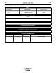
Install a disconnect switch and fuse the circuit with the
recommended lag type fuses. Use an input wire size
according to local requirements or use the following
table . The frame of the unit must be grounded.
WARNING