RETURN TO MAIN MENU IM586-B STT-10 Head & Controls August, 2007 Boom Mount or Bench Models For use with: STT-10 Control - Boom Mount Code 10447, 10832 10 Series Wire Drive - Boom Mount Code 10443, 10763, 10818 STT-10 Boom Package Code 10448 Synergic 7F Wire Drive Code 10190, 10191 STT-10 - Bench Model Code 10446, 10766, 10821 STT-10 - Zipline Boom Package Code 10499, 10500, 10773 Safety Depends on You Lincoln arc welding and cutting equipment is designed and built with safety in mind.
i i SAFETY WARNING CALIFORNIA PROPOSITION 65 WARNINGS Diesel engine exhaust and some of its constituents are known to the State of California to cause cancer, birth defects, and other reproductive harm. The Above For Diesel Engines The engine exhaust from this product contains chemicals known to the State of California to cause cancer, birth defects, or other reproductive harm. The Above For Gasoline Engines ARC WELDING CAN BE HAZARDOUS.
ii ii SAFETY ARC RAYS can burn. ELECTRIC SHOCK can kill. 3.a. The electrode and work (or ground) circuits are electrically “hot” when the welder is on. Do not touch these “hot” parts with your bare skin or wet clothing. Wear dry, hole-free gloves to insulate hands. 3.b. Insulate yourself from work and ground using dry insulation. Make certain the insulation is large enough to cover your full area of physical contact with work and ground.
iii iii SAFETY WELDING and CUTTING SPARKS can cause fire or explosion. 6.a. Remove fire hazards from the welding area. If this is not possible, cover them to prevent the welding sparks from starting a fire. Remember that welding sparks and hot materials from welding can easily go through small cracks and openings to adjacent areas. Avoid welding near hydraulic lines. Have a fire extinguisher readily available. 6.b.
iv iv SAFETY PRÉCAUTIONS DE SÛRETÉ Pour votre propre protection lire et observer toutes les instructions et les précautions de sûreté specifiques qui parraissent dans ce manuel aussi bien que les précautions de sûreté générales suivantes: Sûreté Pour Soudage A LʼArc 1. Protegez-vous contre la secousse électrique: a. Les circuits à lʼélectrode et à la piéce sont sous tension quand la machine à souder est en marche.
v v Thank You for selecting a QUALITY product by Lincoln Electric. We want you to take pride in operating this Lincoln Electric Company product ••• as much pride as we have in bringing this product to you! CUSTOMER ASSISTANCE POLICY The business of The Lincoln Electric Company is manufacturing and selling high quality welding equipment, consumables, and cutting equipment. Our challenge is to meet the needs of our customers and to exceed their expectations.
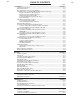
vi TABLE OF CONTENTS Page Installation .......................................................................................................Section A Technical Specifications .......................................................................................................A-1 General Description..............................................................................................................A-2 Recommended Processes and Equipment ..........................................................
vii TABLE OF CONTENTS Page ...... Diagrams ..........................................................................................................Section F Wiring (STT-10 Control).........................................................................................F-1 Wiring (10 Series Wire Drive) ..........................................................................F-2, F3 Dimension Prints ......................................................................................
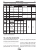
A-1 A-1 INSTALLATION TECHNICAL SPECIFICATIONS – STT-10 Heads & Controls SPEC.# WIRE DRIVE OR WIRE DRIVE SECTION OF FEEDER LOW SPEED RATIO HIGH SPEED RATIO TYPE Speed K1563-1Δ, 10 Series 35-500 IPM K1563-3 Boom Mount (0.89-12.7 m/m) Wire Size Solid Cored .025 - 3/32 in. .030 - .120 in (0.6 - 2.4 mm) (0.8 - 3.0 mm) K679-1 Std Drive Synergic 7F* 50 - 770 IPM Boom Mount (1.27 - 19.5 m/m) .025 - 1/16 in. (0.6 - 1.
A-2 A-2 INSTALLATION The 10 Series Wire Drive assemblies include a heavy duty head with an externally changeable gear ratio and 4 driven roll drives housed together in a single combination mounting and connection box. Gun adapters are available to permit use with a variety of standard welding guns. Available Models: The STT-10 Wire Feeder system is available configured in both Bench and Boom models.
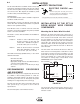
A-3 A-3 INSTALLATION Mounting the STT-10 Control Box (K1565-2) Mounting Synergic 7F Wire Drive Unit (Removed from the wire drive unit.) (See Figure A.3) Mount the wire feed unit by means of the insulated mounting bracket attached to the bottom of the gearbox. Reference L9777 (included with Drive unit) to find the size and location of the mounting holes. The gearbox assembly is electrically “hot” when the gun trigger is pressed.
A-4 INSTALLATION Electrode Routing The electrode supply may be either from reels, ReadiReels, spools, or bulk packaged drums or reels. Observe the following precautions: 2) Remove the Phillips head screw retaining the pinion gear to be changed and remove the gear. If the gear is not easily accessible or difficult to remove, remove the feedplate from the gearbox. To remove feedplate: a) Loosen the clamping collar screw using a 3/16" Allen wrench.
A-5 INSTALLATION WIRE FEED DRIVE ROLL KITS NOTE: The maximum rated solid and cored wire sizes for each wire drive head and selected drive ratio is shown on the SPECIFICATIONS in the front of this section. The electrode sizes that can be fed with each roll and guide tube are stenciled on each part. Check the kit for proper components. Synergic 7F Wire Drives (K679) use 4-Roll drive roll kits with 2 driven rolls, per Table C.1 in ACCESSORIES.
A-6 INSTALLATION 6) Install each drive roll by pushing over shaft until it butts up against locating shoulder on the drive roll shaft. (Do Not exceed maximum wire size rating of the wire drive). 7) Install Outer Wire Guide by sliding over locating pins and tightening in place. 8) Engage upper drive rolls if they are in the “open” position and close Pressure Door. TO SET IDLE ROLL PRESSURE, see “Idle Roll Pressure Setting” in OPERATION.
A-7 A-7 INSTALLATION Gun Cable Connection with Fast-Mate Connection 1. Check that the drive rolls, feeder guide tubes and gun connector guide tube are appropriate for the electrode size being used. If necessary, change them per “Wire Drive Roll Kits” in this section. 2. Connect gun to gun connector making sure all pins and gas tube line up with appropriate holes in connector. Tighten gun by turning large nut on gun cable clockwise.
A-8 A-8 INSTALLATION Work Cable ELECTRICAL INSTALLATION Connect a work lead of sufficient size and length (per the following table) between the proper output terminal on the power source and the work. Be sure the connection to the work makes tight metal-to-metal electrical contact. WARNING ELECTRIC SHOCK can kill. • Do not touch electrically live parts such as output terminals or internal wiring.
A-9 INSTALLATION A-9 When installed and properly configured, the K1561-1 Robotics Interface Module allows complete control of the welding process from the robot controller. OPTIONAL FEATURES INSTALLATION K1758 Input Cable Assembly The Lincoln Electric Companyʼs Automation Center should be contacted for questions regarding installation or operation of the Robotics Interface Module. See “Electrical Installation” for instructions.
B-1 B-1 OPERATION Setting the DIP Switch OPERATING INSTRUCTIONS Safety Precautions The DIP switch is labeled with an “ON” arrow showing the on direction for each of the 8 individual switches in the DIP switch (S1). The functions of the switch are also labeled and set as described below: WARNING ELECTRIC SHOCK can kill. • Do not touch electrically live parts such as output terminals or internal wiring.
B-2 B-2 OPERATION 4-Step Trigger Mode Operation Selection S1 switch 6 ON = Security mode ON Head The STT-10 Control is set up for 4-Step Trigger mode operation with or without weld current interlock by setting S1 DIP switch 5 (Labeled “4”).
B-3 B-3 OPERATION KEYPAD AND DISPLAY OPERATION LINCOLN COLD FEED FORWARD R A COLD FEED REVERSE GAS PURGE WFS PEAK BACKGROUND A REMOTE B PROCEDURE CURRENT Dual procedure settings, including; trigger mode, cold feed speed, Run-in and weld speed and current, timers ranges and acceleration are automatically saved when power is removed. This feature does not require batteries and when power is restored it will automatically return all settings to the state they were in when power was removed.
B-4 OPERATION Trigger Mode Selection Trigger Mode Select key - enables operator to choose mode of operation shown by the indicator lights. Pressing key causes mode lights to sequence (top to bottom) starting from the current indicated selection. COLD FEED 2-STEP STD When burnback spot, or gas timers are selected the current display shows the time setting in seconds, as indicated by “SEC” displayed on the speed display. The times are set using the top encoder knob.
B-5 OPERATION RANGE PEAK MAX PEAK MIN BACKGROUND MAX Range Select key - enables operator to choose which weld parameter to set the maximum or minimum range. Pressing the key causes the range mode lights to sequence (top to bottom) starting from the current indicated selection. The range settings can be set independently for each procedure. Top Light - PEAK MAX - Indicates that the maximum peak current setting is being displayed on the top LED display. This parameter is settable from 17 to 464 amps.
B-6 B-6 OPERATION WIRE REEL LOADING - READI-REELS, SPOOLS OR COILS To Mount a 30 Lb. (14 kg) Readi-Reel Package (Using the Molded Plastic K363-P Readi-Reel Adapter:) The Spindle should be located in the LOWER mounting hole. 1) Depress the Release Bar on the Retaining Collar and remove it from the spindle. 2) Place the Adapter on the spindle. 3) Re-install the Retaining Collar. Make sure that the Release Bar “pops up” and that the collar retainers fully engage the retaining groove on the spindle.
B-7 B-7 OPERATION To Mount a 50-60 Lb. (22.7-27.2 kg) Coil: (Using K1504-1 Coil Reel) (For 50-60 lb ReadiReels a K438 Readi-Reel Adapter must be used). FEEDING ELECTRODE AND BRAKE ADJUSTMENT 1) Turn the Reel or spool until the free end of the electrode is accessible. The Spindle must be located in the UPPER mounting hole. 1) With the K1504-1 Coil Reel mounted on to the 2" (51 mm) spindle (or with reel laying flat on the floor) loosen the spinner nut and remove the reel cover. (See Figure B.2).
B-8 B-8 OPERATION 1) Press end of gun against a solid object that is electrically isolated from the welder output and press the gun trigger for several seconds. 2) If the wire "birdnests", jams, or breaks at the drive roll, the drive roll pressure is too great. Back the pressure setting out 1/2 turn, run new wire through gun, and repeat above steps. 3) If the only result is drive roll slippage, disengage the gun, pull the gun cable forward about 6" (150 mm).
B-9 B-9 OPERATION WIRE REEL CHANGING At the end of a coil, remove the last of the old electrode coil from the conductor cable by either pulling it out at the nozzle end of the gun or by using the following procedure: 1) Cut the end of the electrode off at the gun end. Do not break it off by hand because this puts a slight bend in the wire making it difficult to pull it back through the nozzle.
C-1 C-1 ACCESSORIES TABLE C.1 – DRIVE ROLL AND GUIDE TUBE KITS Wire Size 4-Roll DH Drive (4-Driven) 4-Roll Single Drive (2-Driven) Solid & (Cored) Steel Electrode 0.023” - 0.025” (0.6 mm) KP1505 - 030S KP655 - 025S 0.030” (0.8 mm) KP1505 - 030S KP655 - 030S 0.035” (0.9 mm) KP1505 - 035S KP655 - 035S 0.040” (1.0 mm) KP1505 - 040S KP655 - 035S 0.040” (1.0 mm) KP1505 - 045S KP655 - 035S 0.045” (1.2 mm) KP1505 - 045S KP655 - 052S 0.045”(Cored) (1.
C-2 ACCESSORIES K1758-”L” INPUT CABLE ASSEMBLY Consists of an 8-conductor control cable with a 14-pin plug, a 6-conductor control cable with a 10-pin plug, and an electrode cable with Twist-Mate™ connector. It is rated at 300 amps, 60% duty cycle and is available in lengths of 10 ft. (3 mm), 25 ft. (7.6 m), and 50 ft. (15 m). K2147 CONTROL CABLE AND WELD CABLE Consists of an 8-conductor control cable with a 14-pin plug, a 6-conductor control cable with a 10-pin plug, and a co-axil weld cable.
C-3 ACCESSORIES Coil Adapter: C-3 K206, K289, and K309 K1504-1 Permits 50 lb to 60 lb (22.7-27.2 Kg.) require only the installation of a K1500-1 connector in the STT-10 wire feeder. Coils to be mounted on 2: (51 mm) O.D. spindles. NON-LINCOLN GUNS K435 Permits 14 lb. (6 kg) Innershield coils to be mounted on 2" (51 mm) O.D. spindles. K468 Permits 8" (203 mm) O.D. spools to be mounted on 2" (51 mm) O.D. spindles. : K363P Adapts Lincoln Readi-Reel coils of electrode 30 lb. (14 kg) and 22 lb.
C-4 ACCESSORIES C-4 GUN AND CABLE ASSEMBLIES K684 Magnum "Super Cool" FM water cooled The following Lincoln gun and cable assemblies are compatible with 10 Series Wire Feed heads with appropriate K1500 Gun Adapter: GMAW gun and cable assemblies are rated 450 amps, 100% duty cycle (CO2). (Consult sales specifications for appropriate models) K126 (Requires K1500-1) Innershield gun and cable K498 Magnum 200 FM GMAW gun and cable assemblies are rated for 200 amps 60% duty cycle.
D-1 MAINTENANCE D-1 MAINTENANCE Avoiding Wire Feeding Problems Safety Precautions Wire feeding problems can be avoided by observing the following gun handling and feeder set up procedures: • Do not kink or pull cable around sharp corners. WARNING ELECTRIC SHOCK can kill. • Do not touch electrically live parts such as output terminals or internal wiring.
E-1 TROUBLESHOOTING E-1 HOW TO USE TROUBLESHOOTING GUIDE WARNING Service and Repair should only be performed by Lincoln Electric Factory Trained Personnel. Unauthorized repairs performed on this equipment may result in danger to the technician and machine operator and will invalidate your factory warranty. For your safety and to avoid Electrical Shock, please observe all safety notes and precautions detailed throughout this manual.
E-2 E-2 TROUBLESHOOTING Observe all Safety Guidelines detailed throughout this manual PROBLEMS (SYMPTOMS) POSSIBLE CAUSE RECOMMENDED COURSE OF ACTION Rough wire feeding or wire not feed- 1. Gun cable kinked and/or twisted. ing, but drive rolls are turning. 2. Wire jammed in gun and cable. 3. Check for current position of drive rolls relative to split wire guide groove. 4. Drive rolls may not be seated properly. 5. Gun cable dirty. 6. Worn drive roll. 7. Worn nozzle or cable liner. 8.
E-3 E-3 TROUBLESHOOTING Observe all Safety Guidelines detailed throughout this manual PROBLEMS (SYMPTOMS) POSSIBLE CAUSE RECOMMENDED COURSE OF ACTION Motor does not turn when trigger is 1. The wire drive motor may be pulled. overloaded. "Hxx" will be displayed on the WFS display, where "xx" is the number of seconds until the wire drive attempts to run again. 2. A jumper plug or K1558-1 Remote Switch Interface Module must be properly installed into connector J5. 3.
E-4 E-4 TROUBLESHOOTING Observe all Safety Guidelines detailed throughout this manual PROBLEMS (SYMPTOMS) POSSIBLE CAUSE RECOMMENDED COURSE OF ACTION Gas purge key does not operate the 1. The connector from the control gas solenoid, but gas flow does p.c. board to the display p.c. occur while welding. board or the connector from the display p.c. board to the keypad are loose or improperly inserted. 2. Damaged keypad 3. Damaged display p.c. board. 4. Damaged control p.c. board.
E-5 E-5 TROUBLESHOOTING Observe all Safety Guidelines detailed throughout this manual PROBLEMS (SYMPTOMS) POSSIBLE CAUSE RECOMMENDED COURSE OF ACTION Pressing the trigger key has no 1. The connector from the control effect while not welding. p.c. board to the display p.c. board or the connector from the display p.c. board to the keypad are loose or improperly inserted. 2. Damaged keypad 3. Damaged display p.c. board. 4. Damaged control p.c. board. Pressing the control key has no 1.
E-6 E-6 TROUBLESHOOTING Observe all Safety Guidelines detailed throughout this manual PROBLEMS (SYMPTOMS) POSSIBLE CAUSE RECOMMENDED COURSE OF ACTION Displays & LEDʼs on keypad are 1. The connectors from the control off. The green and red LEDʼs on the p.c. board to the display p.c. control p.c. board are both blinking board are loose or improperly at about one second intervals. inserted. 2. Damaged display p.c. board. 3. Damaged control p.c. board. Displays & LEDʼs on keypad are 1. Damaged control p.
E-7 TROUBLESHOOTING E-7 Observe all Safety Guidelines detailed throughout this manual PC BOARD TROUBLESHOOTING GUIDE - CONTROL P.C. BOARD c. If PC board is visibly damaged mechanically, inspect for cause, then remedy before installing a replacement PC board. WARNING If there is damage to the PC board or if replacing PC board corrects problem, return it to the local Lincoln Electric Field Service Shop. ELECTRIC SHOCK can kill. • Have a qualified individual install and service this equipment.
NOTE: This diagram is for reference only. It may not be accurate for all machines covered by this manual. The specific diagram for a particular code is pasted inside the machine on one of the enclosure panels. If the diagram is illegible, write to the Service Department for a replacement. Give the equipment code number..
NOTE: This diagram is for reference only. It may not be accurate for all machines covered by this manual. The specific diagram for a particular code is pasted inside the machine on one of the enclosure panels. If the diagram is illegible, write to the Service Department for a replacement. Give the equipment code number.
NOTE: This diagram is for reference only. It may not be accurate for all machines covered by this manual. The specific diagram for a particular code is pasted inside the machine on one of the enclosure panels. If the diagram is illegible, write to the Service Department for a replacement. Give the equipment code number..
F-4 CONNECTION DIAGRAMS STT-10 F-4
STT-10 6.00 3.00 2.25 10.40 4.08 14.71 5/16-18UNC-2B (4 PLACES) 11.00 2.42 4.44 5.25 6.55 M18904 7-2000 WIRE DRIVE DIMENSION PRINT 7.81 12.
(1 5.30) (30.35) BENCH MODEL DIMENSION PRINT STT-10 7-2000 M 18903 (14.43) (5.25) (10.66) (20.
14.65 STT-10 10.10 12.75 R .141 (3 SLOTS) 14.67 2.63 2.80 GRAPHICS SHOWN REPRESENT M17869-1. 5.25 10.92 13.75 5-2-97• M18299 4.58 3 YEAR WARRANTY WARNING 4.
NOTES STT-10
NOTES STT-10
● Do not touch electrically live parts or WARNING Spanish AVISO DE PRECAUCION French ATTENTION German WARNUNG Portuguese ATENÇÃO ● Keep flammable materials away. ● Wear eye, ear and body protection. ● Mantenga el material combustible ● Protéjase los ojos, los oídos y el electrode with skin or wet clothing. ● Insulate yourself from work and ground. ● No toque las partes o los electrodos bajo carga con la piel o ropa mojada. ● Aislese del trabajo y de la tierra.
● Keep your head out of fumes. ● Use ventilation or exhaust to ● Turn power off before servicing. ● Do not operate with panel open or guards off. remove fumes from breathing zone. ● Los humos fuera de la zona de res- piración. ● Mantenga la cabeza fuera de los humos. Utilice ventilación o aspiración para gases. ● Gardez la tête à l’écart des fumées. ● Utilisez un ventilateur ou un aspira- ● Desconectar el cable de ali- mentación de poder de la máquina antes de iniciar cualquier servicio.
• World's Leader in Welding and Cutting Products • • Sales and Service through Subsidiaries and Distributors Worldwide • Cleveland, Ohio 44117-1199 U.S.A. TEL: 216.481.8100 FAX: 216.486.1751 WEB SITE: www.lincolnelectric.