
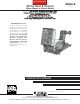
User Guide


A-2
INSTALLATION
STT-10
A-2
The 10 Series Wire Drive assemblies include a heavy duty
head with an externally changeable gear ratio and 4 driven
roll drives housed together in a single combination mounting
and connection box. Gun adapters are available to permit
use with a variety of standard welding guns.
Available Models:
The STT-10 Wire Feeder system is available configured in
both Bench and Boom models.
Bench Models consists of an STT-10 control and a 10
Series wire drive assembly premounted on a platform
with a 2" O.D. spindle mounting.
Boom Models consist of a STT-10 control and a wire drive
designed to be mounted separately and joined by available
head to control cable assemblies.
The head to control cable assemblies are available as
stated below:
K1567-”L”
Includes a control cable with a 14-pin
ms style connection on each end, and
a weld cable. Available in lengths “L”
of 16, 20 or 25 ft. (4.9, 6.1 or 7.6 m)
K681-”L” Same as above but does not include
weld cable available in lengths “L” of
12, 16 or 25 ft. (3.6, 4.9 or 7.6 m).
STT-10 Boom Package (K1568-Series) is also avail-
able which includes:
• STT-10 Control Box
• 10 Series Wire Drive
• Appropriate length Control and Weld Cables to
connect Control to Wire Drive
• Accessories specific to the Boom package
ordered
RECOMMENDED PROCESSES
AND EQUIPMENT
GMAW is the only process supported by the STT-10.
It is similar to “short-circuiting transfer” or “short arc”
welding in that metal transfer is by physical contact.
Non-shorting modes such as axial spray and pulse
welding are not supported by STT technology.
The wire type and size range for the wire drive used,
and speed range, are given in the Technical
Specifications.
The STT-10 requires a STT-II Power Source.
SAFETY PRECAUTIONS
INSTALLATION OF THE STT-10
BOOM MOUNT WIRE FEEDER
COMPONENTS
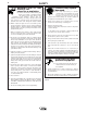
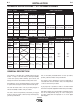
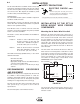
Mounting the 10 Series Wire Drive Unit
Mount the 10 Series wire drive unit to the boom or
structure using the four 5/16-18 threaded mounting
holes located on the bottom of the drive connection
box. See Figure A.1 for the size and location of the
mounting holes. The feed plate and cover assembly is
electrically "hot" when the gun trigger is pressed.
Therefore, make certain the feed plate and cover do
not come in contact with the structure on which the
unit is mounted.
The wire drive unit should be mounted so that the
drive rolls are in a vertical plane so dirt will not collect
in the drive roll area. Pivot the feed plate so it will
point down at an angle so the wire feed gun cable will
not be bent sharply as it comes from the unit. See
“Procedure for setting angle of Feed Plate” in the
OPERATION section of this manual.
FIGURE A.1
The boom wire drive speed selection must be set to
match the STT-10 control. See “Wire Drive Speed Range
Selection” section.
ELECTRIC SHOCK can
kill.
• Turn the input power off at the power source
disconnect switch before attempting to connect
the input power to the STT-10 Control.
• Only qualified personnel should perform this installation.
----------------------------------------------------------------------------------------
5/16-18 THREAD
2.25
2.25
FEED PLATE
DOOR OPEN
5.00
10.50
14.50
3.00
6.00
11.00
BOTTOM FRONT