IM697-B RED-D-ARC MX 300 For use with machines having Code Numbers: 10799 11149 11855 September, 2011 ( RETURN TO MAIN MENU OPERATOR’S MANUAL Red-D-Arc Spec-Built Welding Equipment This RED-D-ARC welder is built to RED-D-ARC Extreme Duty design specifications by Lincoln Electric. Safety Depends on You This welder is designed and built with safety in mind. However, your overall safety can be increased by proper installation ... and thoughtful operation on your part.
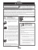
i i SAFETY WARNING CALIFORNIA PROPOSITION 65 WARNINGS Diesel engine exhaust and some of its constituents are known to the State of California to cause cancer, birth defects, and other reproductive harm. The Above For Diesel Engines The engine exhaust from this product contains chemicals known to the State of California to cause cancer, birth defects, or other reproductive harm. The Above For Gasoline Engines ARC WELDING CAN BE HAZARDOUS.
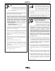
ii ii SAFETY ELECTRIC SHOCK can kill. 3.a. The electrode and work (or ground) circuits are electrically “hot” when the welder is on. Do not touch these “hot” parts with your bare skin or wet clothing. Wear dry, hole-free gloves to insulate hands. 3.b. Insulate yourself from work and ground using dry insulation. Make certain the insulation is large enough to cover your full area of physical contact with work and ground.
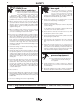
iii iii SAFETY WELDING and CUTTING SPARKS can cause fire or explosion. 6.a. Remove fire hazards from the welding area. If this is not possible, cover them to prevent the welding sparks from starting a fire. Remember that welding sparks and hot materials from welding can easily go through small cracks and openings to adjacent areas. Avoid welding near hydraulic lines. Have a fire extinguisher readily available. 6.b.
iv SAFETY iv PRÉCAUTIONS DE SÛRETÉ 6. Eloigner les matériaux inflammables ou les recouvrir afin de prévenir tout risque dʼincendie dû aux étincelles. Pour votre propre protection lire et observer toutes les instructions et les précautions de sûreté specifiques qui parraissent dans ce manuel aussi bien que les précautions de sûreté générales suivantes: 7. Quand on ne soude pas, poser la pince à une endroit isolé de la masse.
v v Thank You for selecting one of our QUALITY products. We want you to take pride in operating this product ••• as much pride as we have in bringing this product to you! CUSTOMER ASSISTANCE POLICY The business of our company is manufacturing and selling high quality welding equipment. Our challenge is to meet the needs of our customers and to exceed their expectations. On occasion, purchasers may ask us for advice or information about their use of our products.
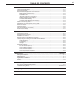
vi TABLE OF CONTENTS Page Installation.......................................................................................................................Section A Technical Specifications .......................................................................................................A-1 Product Description. .............................................................................................................A-2 Recommended Equipment and Processes ..........................................
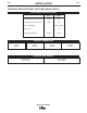
A-1 A-1 INSTALLATION TECHNICAL SPECIFICATIONS - RED-D-ARC MX350 (K1823-1) ELECTRICAL SPECIFICATIONS AMPS (DC+) VOLTS (DC+) Output Rating @ 50ºC (122ºF) 350 34 Input Rating @ 50ºC (122ºF) 165 80 Max. Input Range 50-113 (Peak) Max. O.C.V. 78 Output Preset Range 30-350 15-40 PHYSICAL DIMENSIONS HEIGHT 11.6 in 295 mm WIDTH 10.0 in 254 mm DEPTH 21.5 in 546 mm NET WEIGHT 59.5 lbs. 27.0 kg.
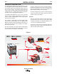
A-2 A-2 INSTALLATION Versatile PRODUCT DESCRIPTION The RED-D-ARC MX350 converter (K1823-1) is part of a Multi-Weld system, ideally suited for construction site welding, which uses a single DC power source, as the only input supply, and provides independent full range control of up to 350A continuous with each converter arc for + polarity stick and wire processes, as well as for arc-air gouging.(See Figure 1). • Constant Current (CC) mode for stick and gouging.
A-3 A-3 INSTALLATION • Converter welding controls are near the arc without long control cables, and a receptacle is provided for an optional remote for even closer user output control. RECOMMENDED EQUIPMENT AND PROCESSES MULTI-SYSTEM POWER SOURCE Simple • Easy installation with 10 ft. (3m) work clip lead and user preference quick-connect "pigtails" for input and electrode weld cables.
A-4 A-4 INSTALLATION REMOTE OUTPUT CONTROL OPTIONS INSTALLATION The RED-D-ARC MX350 is provided with a 3-pin remote receptacle. QUICK-CONNECT "PIG-TAILS" CV MODE WIRE WELDING The Converter in CV mode was designed for use with an arc-powered wire feeder like the LN-25. The Converter output is always "hot" when the mode switch is not OFF, so it is recommended that the LN25 model be equipped with the internal contactor in order to have a "cold" electrode when the gun trigger is released.
A-5 INSTALLATION To connect the "pig-tail" cables to the Converter: 1. Stand the Converter vertically on its rear handle and skid to gain access to the bottom stud covers, then remove the two 0.25"(6.3mm) screws securing each cover and fold out the cover insulation. 2. Route the appropriate "pig-tail" cable lug ends under the skid rail (for strain-relief) through the desired front and/or rear corner channels to the exposed 0.5"(13mm) stud, and remove the flange nut with a .75"(19mm) wrench.
A-6 A-6 INSTALLATION INTER-CONNECTION OF CONVERTERS Power Source (Volts x Amp) capacity > 1.
A-7 A-7 INSTALLATION Converters on Cable Table .1 Cable Size AWG (mm2 ) 1 2 3 4 5 1/0 (50) 2/0 (70) 3/0 (95) 4/0 (120) 2x3/0 (2x95) The output "Electrode" cable should be 2/0 AWG (70mm2 ) if sized for rated output up to 200 ft.(61m) from the Converter. If paralleled, the output cable to the arc should be 4/0(120mm2).
B-1 B-1 OPERATION Figure 3 The numbered items of Figure 3, above, match the numbered items described below: 1 3 4 5 6 2 8 9 10 7 WORK + INPUT ELECTRODE + + FRONT PANEL CONTROLS • Only VOLTS digital meter is lit displaying the preset voltage setting These few instruments are basic to the operation and monitoring of the Converter.
B-2 OPERATION Average Amps for about 7 seconds after welding stops in CC and CV modes only. • The 5 second memory display is indicated by the displayʼs left-most decimal point blinking, and is interrupted if arc is restarted. Accuracy of Actual Amps is within 3%, and typically within 10 amps of Preset. • An Actual Amps meter calibration adjustment trimmer is provided. ( See MAINTENANCE section). Two front screws secure the meter bezel which holds a replaceable spatter shield lens (Lincoln part no.
B-3 B-3 OPERATION PARALLELED CONVERTERS STORAGE RED-D-ARC MX350 converters that are paralleled (see INTER-CONNECTION OF CONVERTERS in the INSTALLATION section) must each be set up in the same manner in order to manage the arc current drawn from each: 1) Set to CC mode with CC SLOPE switch set to STICK/GOUGE. 2) Preset Output Controls of both paralleled Converters to ~1/2 desired total Amps.
B-4 OPERATION OVER-CURRENT PROTECTION The max. output current of the RED-D-ARC MX350 is electronically limited, to protect internal power components, so as not to exceed about 375 amps average and 500 amps peak. When the current load starts to exceed these limits the output is reduced (lower voltage) to sustain these max. levels, until the current is reduced. even to a shorted output. B-4 During Over-Temperature Shutdown the panel displays will be as appropriate for the non-welding mode.
D-1 MAINTENANCE SAFETY PRECAUTIONS WARNING Have qualified personnel do the maintenance work. Always use the greatest care when working near moving parts. If a problem cannot be corrected by following the instructions, take the machine to the nearest Lincoln Field Service Shop. -----------------------------------------------------------------------ELECTRIC SHOCK can kill. • Do not touch electrically live parts or electrode with skin or wet clothing.
D-2 MAINTENANCE SERVICE The RED-D-ARC MX350 was designed for easy service using quick to replace components, and assembly modules which could be simply swapped out at the job site to minimize down time, and so more prolonged troubleshooting and repair of the module may be done later on the service bench. D-2 Tunnel Module (item (2) is removed from the Base Module assembly by removing the four bottom accessed screws and disconnecting the two sealed harness plugs and power leads.
E-1 TROUBLESHOOTING E-1 HOW TO USE TROUBLESHOOTING GUIDE WARNING Service and Repair should only be performed by Trained Personnel. Unauthorized repairs performed on this equipment may result in danger to the technician and machine operator and will invalidate your factory warranty. For your safety and to avoid Electrical Shock, please observe all safety notes and precautions detailed throughout this manual.
E-2 E-2 TROUBLESHOOTING Observe all Safety Guidelines detailed throughout this manual PROBLEMS (SYMPTOMS) Machine completely dead: Input contactor does not pull in, meters are off. POSSIBLE AREAS OF MISADJUSTMENT(S) RECOMMENDED COURSE OF ACTION 1. Check cable connections from (+) Input and Work to power source for loose or faulty connection. 2. Input voltage may be too low. Measure input voltage to machine, should be 50 – 113 VDC. 3. The power switch may be faulty. 4.
E-3 E-3 TROUBLESHOOTING Observe all Safety Guidelines detailed throughout this manual PROBLEMS (SYMPTOMS) Meter turns on, input contactor pulls in, thermal light is off. Machine has no output: POSSIBLE AREAS OF MISADJUSTMENT(S) RECOMMENDED COURSE OF ACTION 1. The output cable connections may be faulty. Check (+) Electrode and Work cable connections. 2. The connections at control box plugs, chopper boards plugs, or Analog Control Power Supply PCB connectors may be faulty. 3.
E-4 E-4 TROUBLESHOOTING Observe all Safety Guidelines detailed throughout this manual PROBLEMS (SYMPTOMS) The meter is not accurate: POSSIBLE AREAS OF MISADJUSTMENT(S) RECOMMENDED COURSE OF ACTION 1. The Analog Control Power Supply PCB or its connections may be faulty. 2. The Weld Control PCB may be faulty. Fan does not run when turning machine on: 1. Fan does not normally run until machine is welding. See Instruction Manual. Fan does not run when welding: 1.
E-5 E-5 TROUBLESHOOTING Observe all Safety Guidelines detailed throughout this manual PROBLEMS (SYMPTOMS) Current changing with arc length in Stick welding: POSSIBLE AREAS OF MISADJUSTMENT(S) RECOMMENDED COURSE OF ACTION 1. Check the CC Slope switch on the recessed panel, it should be set at Stick/Gauge position for Stick welding. 2. Faulty CC Slope switch or connections. 3. Faulty Weld Control PCB. Poor performance on "fast-freeze" 1.
F-1 DIAGRAMS RED-D-ARC MX350 ENHANCED DIAGRAM F-1
F-2 DIAGRAMS RED-D-ARC MX350 ENHANCED DIAGRAM F-2
DIMENSION PRINT - MX350 CONVERTER A DIAGRAMS RED-D-ARC MX350 11321 F-3 F-3
DIMENSION PRINT FOR DISTRIBUTION BOX M19448 C-UF F-4 DIAGRAMS RED-D-ARC MX350 F-4
NOTES RED-D-ARC MX350
NOTES RED-D-ARC MX350
G Keep your head out of fumes. G Use ventilation or exhaust to G Turn power off before servicing. G Do not operate with panel open or guards off. remove fumes from breathing zone. G Los humos fuera de la zona de res- piración. G Mantenga la cabeza fuera de los humos. Utilice ventilación o aspiración para gases. G Gardez la tête à l’écart des fumées. G Utilisez un ventilateur ou un aspira- G Desconectar el cable de ali- mentación de poder de la máquina antes de iniciar cualquier servicio.
G Do not touch electrically live parts or WARNING Spanish AVISO DE PRECAUCION French ATTENTION German WARNUNG Portuguese ATENÇÃO G Keep flammable materials away. G Wear eye, ear and body protection. G Mantenga el material combustible G Protéjase los ojos, los oídos y el electrode with skin or wet clothing. G Insulate yourself from work and ground. G No toque las partes o los electrodos bajo carga con la piel o ropa mojada. G Aislese del trabajo y de la tierra.
• World's Leader in Welding and Cutting Products • • Sales and Service through Subsidiaries and Distributors Worldwide • Cleveland, Ohio 44117-1199 U.S.A. TEL: 216.481.8100 FAX: 216.486.1751 WEB SITE: www.lincolnelectric.